Choreonoid 开始的机器人仿真(第一部分)
Back to Top为了覆盖更广泛的受众,这篇文章已从日语翻译而来。
您可以在这里找到原始版本。
0. 引言
#什么是Choreonoid
#Choreonoid[1] 是由产业技术综合研究所(AIST)开发的开源机器人仿真软件。
截至2025年1月10日的最新版本支持以下操作系统:
- Ubuntu Linux
- Windows
本文使用Ubuntu 22.04。
最初似乎是作为机器人的动作编排工具开发的,其名称结合了 "Choreograph"(编排)和 "Humanoid"(人型机器人)两个词。
目前由株式会社コレオノイド持续开发,源码已在GitHub上公开,详情请见这里[2]。
该仿真器的特点如下:
- 可用作动力学仿真器
- 运行性能流畅
- 通过插件实现高度扩展性
- 可与ROS1及ROS2联动
作者在学生时代曾在研究中使用该仿真器,与动力学仿真器Gazebo相比,其运动流畅性令人印象深刻。
本文将介绍Choreonoid的魅力,并结合使用方法与示例进行展示。
GitHub链接
#1. 开发环境构建
#创建工作目录
#创建将要使用的工作空间目录。
本文将在Home目录内创建一个名为Chorenoid_ws的文件夹。
如果使用其他文件夹名,请相应进行替换。
$ mkdir -p ~/Choreonoid_ws
克隆仓库
#在工作空间目录内克隆Choreonoid的仓库。
$ cd ~/Choreonoid_ws
$ git clone git@github.com:choreonoid/choreonoid.git
安装相关工具
#安装与Choreonoid相关的工具。仓库内存在用于一键安装的bash文件,因此请使用该文件。
所执行的文件会因操作系统而异,请注意文件名后缀。
此次使用适用于Ubuntu22.04的文件。
$ cd ~/Choreonoid_ws/choreonoid/misc/script
$ bash install-requisites-ubuntu-22.04.sh
构建
#进入克隆的源代码目录,并使用CMake进行构建。
# 切换目录
$ cd ~/Choreonoid_ws/choreonoid

# 生成构建系统
$ cmake -S . -B build

# 执行构建(并行构建)
$ cmake --build build --parallel 4
安装
#一般情况下,应用程序通常使用make install等方式安装到/usr/local等目录下,但Choreonoid推荐保留在Home目录内生成的状态[4]。
本文仅将生成的二进制文件所在路径加入到系统路径中。将前节生成的可执行文件路径注册到~/.bashrc文件中。
$ echo "export PATH=$PATH:~/Choreonoid_ws/choreonoid/build/bin" >> ~/.bashrc
重启终端以使上述更改生效后,执行下列命令确认choreonoid能正常启动。
$ choreonoid
开发环境构建完毕。
2. 项目准备
#新建项目文件夹
#本示例中,将使用Choreonoid中公开的三菱重工操纵器机器人 "PA-10"[5](下图)的模型。
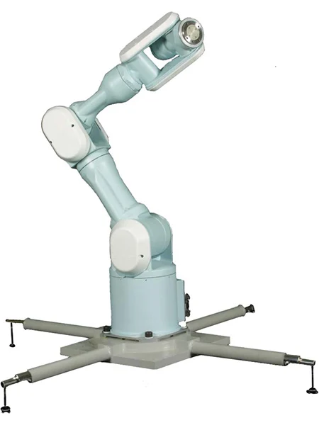 三菱重工 电动通用多轴操纵器 PA-10
首先,在工作目录choreonoid/ext文件夹内创建一个PA10_JointAngleControl文件夹。
在该文件夹中存放项目文件和控制器的源码。
$ mkdir -p ~/Choreonoid_ws/choreonoid/ext/PA10_JointAngleControl
本文中,文件等将存放在现有的choreonoid/ext文件夹内。
尽管可以在Choreonoid内创建任意文件夹,但出于方便起见,本文将在ext文件夹内进行存放。
之后,每个控制器将创建子文件夹,并将相关代码存放其中。
拷贝PA10模型
#PA10的模型文件存放在choreonoid/share/model/PA10文件夹内。
将该文件夹内的内容复制到刚创建的PA10_JointAngleControl中,并命名为model文件夹。
$ cd ~/Choreonoid_ws/choreonoid
$ cp -r share/model/PA10 ext/PA10_JointAngleControl/model
文件夹结构应如下所示:
ext/
└── PA10_JointAngleControl/
    └── model/(※ share/model/PA10 的拷贝)
以下展示 model/PA10.body 文件的一部分。
本文件使用YAML语言编写,定义了机器人模型,包括各连接部分的形状、特性、各关节限制和建模文件。
Body文件的参考资料在此,供参考。
https://choreonoid.org/ja/manuals/latest/handling-models/modelfile/yaml-reference.html
format: ChoreonoidBody
formatVersion: 1.0
angleUnit: degree   # 角度单位
name: PA10

links:  # 构成连接列表
  -
    name: BASE          # 连接名称(根连接)
    jointType: fixed    # 固定连接
    mass: 3.04          # 质量[kg]
    centerOfMass: [ 0, 0, 0.075 ]   # 重心位置
    inertia: [  # 惯性矩
      1, 0, 0,
      0, 1, 0,
      0, 0, 1 ]
    elements:
      Visual: { resource: { uri: "parts/BASE.wrl" } }
      Collision:
        shape:
          rotation: [ 1, 0, 0, 90 ]
          translation: [ 0, 0, 0.1 ]
          geometry:
            type: Cylinder
            height: 0.2
            radius: 0.115
  -
    name: J1                    # 连接名称
    parent: BASE                # 父连接
    jointType: revolute         # 旋转连接(关节)
    jointAxis: [ 0, 0, 1 ]      # 旋转轴
    jointId: 0                  # 关节ID
    translation: [ 0, 0, 0.2 ]  # 相对于父连接的位置
    rotation: [ 0, 0, 1, 0 ]    # 相对于父连接的姿态
    jointRange: [ -177, 177 ]   # 限制角度
    jointVelocityRange: [ -180, 180 ] # 限制角速度
    rotorInertia: 3.0E-4        # 转子惯性矩
    mass: 9.78                  # 质量
    centerOfMass: [ 0, 0, 0.14818 ] # 重心位置
    inertia: [
      1, 0, 0,
      0, 1, 0,
      0, 0, 1 ]
    elements:   # 连接的组成元素节点列表
      Visual: { resource: { uri: "parts/J1.wrl" } } # 指定模型文件
      Collision:  # 碰撞模型
        elements: # 组成元素
          -
            type: Shape
            rotation: [ 1, 0, 0, 90 ]
            translation: [ 0, 0, 0.01 ]
            geometry:
              type: Cylinder
              height: 0.02
              radius: 0.115
          -
            type: Transform
            translation: [ 0.085, 0, 0.09 ]
            elements: &J1_FRAME
              Shape:
                rotation: [ 1, 0, 0, 90 ]
                geometry:
                  type: Capsule
                  height: 0.062
                  radius: 0.058
          -
            type: Transform
            translation: [ -0.09, 0, 0.09 ]
            elements: *J1_FRAME
  -
    name: J2
    parent: J1
    jointType: revolute
    # (以下略)
下表列出了PA10各关节的最小值和最大值。
| 关节名称 | 最小值[deg] | 最大值[deg] |
|---|---|---|
| J1 | -177.0 | 177.0 |
| J2 | -94.0 | 94.0 |
| J3 | -174.0 | 174.0 |
| J4 | -137.0 | 137.0 |
| J5 | -255.0 | 255.0 |
| J6 | -165.0 | 165.0 |
| J7 | -255.0 | 255.0 |
| HAND_L | -0.030 | 0.030 |
| HAND_R | -0.030 | 0.030 |
启动Choreonoid
#既然已经构建好Choreonoid的开发环境,接下来让我们迅速准备仿真。
首先,在终端中启动Choreonoid。
$ choreonoid
添加世界
#启动Choreonoid后,进行仿真准备。
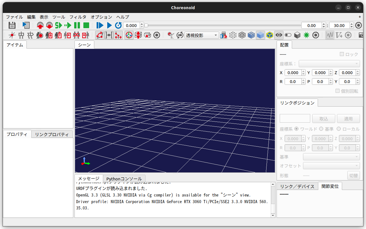
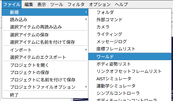
首先选择“文件”标签 -> “新建” -> “世界”,并将世界名称设为“World”。
世界是所有元素的父元素。因此,机器人及仿真需要在世界下创建。
在元素树中选择父元素后添加元素,可以将其作为子元素进行配置。
此时暂时保存项目文件。选择“文件”->“另存项目”。
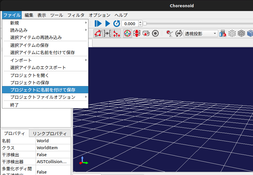
在下列位置创建“project”文件夹,并将文件保存为“PA10_JointAngleControl”。
ext/
└── PA10_JointAngleControl/
    ├── model/
    └── project/                          <--- 新建
        └── PA10_JointAngleControl.cnoid  <--- 保存的文件
添加Body文件
#将Body文件作为子元素添加到“World”中。
保持选中“World”,选择“文件”->“导入”->“Body”。
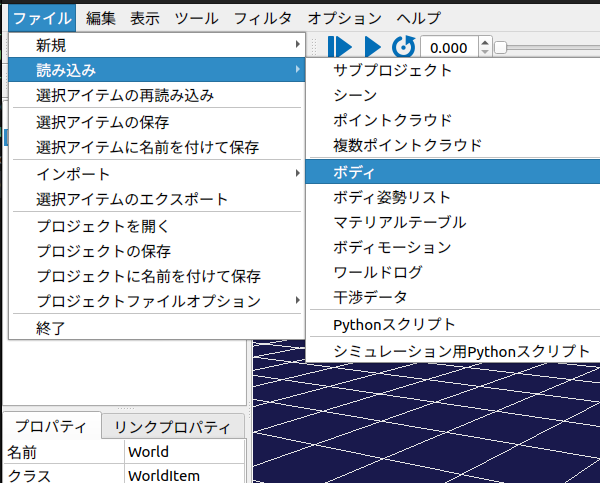
选择之前复制到model文件夹中的“PA10.body”。
选择后,屏幕上将显示PA10。
控制器设置
#为控制目标模型设置控制器。
首先,在选中PA10(控制目标模型)的状态下,选择“文件”->“新建”->“简单控制器”。
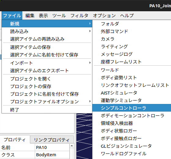
在此,将控制器的名称设置为“JointAngleController”。
稍后将在此处设置生成的控制器。
创建仿真器
#世界和控制器的设置到此为止,但还需要创建用于仿真的项目。
选中World,选择“文件”->“新建”->“AIST仿真器”。
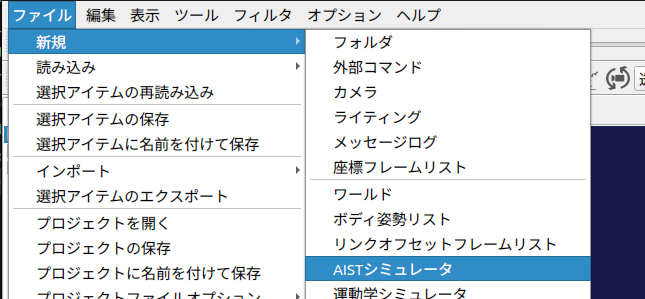
名称设为“AISTSimulator”。
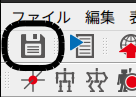
保存项目
#设置完成后,点击左上角的“Save”图标,将当前项目结构保存到文件中。
项目准备工作到此完成。请暂时关闭Choreonoid。
最终项目内的结构如下图所示。
3. 创建输出目标关节角度指令的控制器
#Choreonoid支持的控制器类型
#在Choreonoid中,可以使用以下控制器来驱动机器人:
- SimpleController
- Choreonoid独有的轻量级控制器
- 使用C++编写
- Python Controller
- 使用Python编写
- BodyIoRTC
- ROS Controller
- Plugin-based Controller
创建源码文件夹和文件
#将开发用于驱动机器人的控制器。
在ext/PA10_JointAngleControl文件夹内,创建源码文件夹、源码文件和CMakeLists.txt。
$ cd ~/Choreonoid_ws/choreonoid/ext/PA10_JointAngleControl
$ mkdir src
$ touch src/PA10_JointAngleController.cpp
$ touch CMakeLists.txt
编辑CMakeLists.txt
#设置将新建的源码文件作为Choreonoid的简单控制器进行构建。
choreonoid_add_simple_controller(PA10_JointAngleController src/PA10_JointAngleController.cpp)
实现控制器
#实现 src/PA10_JointAngleController.cpp。
这次将制作如下的简单控制器:
- 对机器人各轴,使用随机生成的关节角度作为指令值
- 但数值控制在关节限制范围内
- 根据以下时间段赋予关节角度
- t1 = 0.0 ~ 2.5[s]
- t2 = 2.5 ~ 5.0[s]
- t3 = 5.0 ~ 7.5[s]
- t4 = 7.5 ~ 10.0[s]
以下为代码。(GitHub链接这里)
#include <cnoid/SimpleController>
#include <random>

#pragma region Declaration

/// @brief 为PA10的每个关节赋予角度
class PA10_JointAngleController : public cnoid::SimpleController
{
private:
    /// @brief 关节数量
    static const int jointNum = 9;

    /// @brief 模式数量
    static const int patternNum = 4;

    /// @brief PA10模型的关节限制
    const float JointLimit[jointNum] = {177.0, 94.0,  174.0, 137.0, 255.0,
                                        165.0, 255.0, 0.030, 0.030};

    /// @brief 关节角度的模式
    float anglePattern[patternNum][jointNum];

    /// @brief Body指针
    cnoid::BodyPtr ioBody;

    /// @brief 当前仿真时间 [ms]
    double currentTime;

    /// @brief 仿真步长 [ms]
    double timeStep;

    /// 方法
    float generateRandomFloat(float min, float max);
    float deg2rad(float deg);

public:
    /// 方法
    PA10_JointAngleController();
    virtual bool initialize(cnoid::SimpleControllerIO* io) override;
    virtual bool control() override;
};
CNOID_IMPLEMENT_SIMPLE_CONTROLLER_FACTORY(PA10_JointAngleController)

#pragma endregion

#pragma region Implementation

/// @brief 构造函数(未实现)
PA10_JointAngleController::PA10_JointAngleController() {}

/// @brief 在SimpleController启动时执行一次
/// @param io SimpleControllerIO的指针
/// @return 初始化结果
bool PA10_JointAngleController::initialize(cnoid::SimpleControllerIO* io)
{
    // 获取Body指针
    ioBody = io->body();

    // 配置每个关节
    for (int jointId = 0; jointId < jointNum; jointId++)
    {
        cnoid::Link* joint = ioBody->joint(jointId);

        // 将关节设置为角度控制模式
        joint->setActuationMode(cnoid::Link::JointAngle);

        // 启用该关节的输入和输出
        io->enableIO(joint);
    }

    // 初始化当前时间
    currentTime = 0.0;

    // 创建关节角度模式
    // 角度必须在关节限制范围内。
    for (int patternId = 0; patternId < patternNum; patternId++)
    {
        for (int jointId = 0; jointId < jointNum; jointId++)
        {
            anglePattern[patternId][jointId] =
                generateRandomFloat(-JointLimit[jointId], JointLimit[jointId]);
        }
    }

    // 获取仿真步长
    timeStep = io->timeStep();

    return true;
}

/// @brief 每周期执行
/// @return 执行结果
bool PA10_JointAngleController::control()
{
    // 根据当前仿真时间选择模式索引
    int currentPatternIndex;
    if (0 <= currentTime && currentTime < 2.5)
        currentPatternIndex = 0;
    else if (2.5 <= currentTime && currentTime < 5.0)
        currentPatternIndex = 1;
    else if (5.0 <= currentTime && currentTime < 7.5)
        currentPatternIndex = 2;
    else if (7.5 <= currentTime && currentTime < 10.0)
        currentPatternIndex = 3;
    else
        currentPatternIndex = 0;

    // 根据模式索引控制关节角度
    for (int jointId = 0; jointId < jointNum; jointId++)
    {
        // 单位必须为弧度
        ioBody->joint(jointId)->q_target() = deg2rad(anglePattern[currentPatternIndex][jointId]);
    }

    // 计算当前时间
    currentTime += timeStep;

    return true;
}

/// @brief 生成随机浮点数
/// @param min 最小值
/// @param max 最大值
/// @return 生成的值
float PA10_JointAngleController::generateRandomFloat(float min, float max)
{
    if (min > max)
    {
        throw std::invalid_argument("min must be less than or equal to max");
    }

    std::random_device rd;
    std::mt19937 gen(rd());
    std::uniform_real_distribution<float> dis(min, max);

    return dis(gen);
}

/// @brief 将角度转换为弧度
/// @param deg 角度(度)
/// @return 角度(弧度)
float PA10_JointAngleController::deg2rad(float deg)
{
    return deg * M_PI / 180.0f;
}

#pragma endregion
代码解析
#下面对代码中的重要部分进行解析。
initialize方法和control方法
#此次创建的PA10_JointAngleController类继承自cnoid::SimpleControllerIO类。
cnoid::SimpleController类中定义了以下虚函数。
可以在派生类中通过重写实现所需的操作。
| 方法 | 详情 |
|---|---|
configure(cnoid::SimpleControllerConfig* config) |
当SimpleController被添加到Body时执行 |
initialize(cnoid::SimpleControllerIO* io) |
仿真开始前的初始化操作 |
start() |
仿真开始时执行 |
control() |
每个仿真周期执行一次 |
stop() |
仿真停止时执行 |
unconfigure() |
控制器卸载时执行 |
SimpleController类的详细信息请参阅
choreonoid/src/Body/SimpleController.h中的注释。
在此次创建的控制器PA10_JointAngleController中,重写了initialize()和control()两个方法。
在initialize方法中:
- 配置各关节的输入输出
- 创建关节模式
- 获取仿真步长
在control方法中:
- 更新当前时间变量
currentTime - 根据时间切换模式
- 根据模式控制关节角度
对机器人发出运动指令
#控制机器人关节角的流程如下:
- 在initialize方法中获取Body指针
ioBody = io->body();
- 在initialize方法中将每个关节配置为角度控制模式
// 配置每个关节
for (int jointId = 0; jointId < jointNum; jointId++)
{
    cnoid::Link* joint = ioBody->joint(jointId);

    // 将关节设置为角度控制模式
    joint->setActuationMode(cnoid::Link::JointAngle);

    // 启用关节的控制与传感
    io->enableIO(joint);
}
- 在control方法中,将目标角度赋值给
q_target的引用
// 根据模式索引控制关节角度
for (int jointId = 0; jointId < jointNum; jointId++)
{
    // 单位必须为弧度
    ioBody->joint(jointId)->q_target() = deg2rad(anglePattern[currentPatternIndex][jointId]);
}
控制器构建
#在CMakeLists.txt中添加构建SimpleController的描述。
第一个参数指定控制器名称,第二个参数指定控制器的源文件。
choreonoid_add_simple_controller(PA10_JointAngleController src/PA10_JointAngleController.cpp)
编辑完成后,同上文构建choreonoid时一样进行构建。
$ cd ~/Choreonoid_ws/choreonoid
$ cmake --build build --parallel 4
构建完成后,控制器文件将生成在如下位置。
控制器以 .so 文件(共享库)的形式输出。
choreonoid/build/lib/choreonoid-2.2/simplecontroller/PA10_JointAngleController.so
稍后将配置使用该文件。
4. 执行仿真
#启动Choreonoid
#重新打开之前关闭的Choreonoid。
此时,可以通过在命令行的第一个参数中指定project文件来打开项目。
$ cd ~/Choreonoid_ws/choreonoid/ext/PA10_JointAngleControl
$ choreonoid project/PA10_JointAngleControl.cnoid
控制器设置
#在“控制器设置”部分,选中创建的SimpleController项目栏,然后点击屏幕左下的属性栏中的“控制器模块”。
点击后出现的图标,再点击选择刚生成的SimpleController文件。
生成位置如下:
choreonoid/build/lib/choreonoid-2.2/simplecontroller/PA10_JointAngleController.so
同时,将“重新加载”属性改为TRUE。
这样可以省去每次构建后重新设置SimpleController的麻烦。
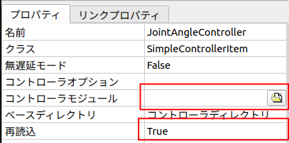
完成此步骤后,保存项目。
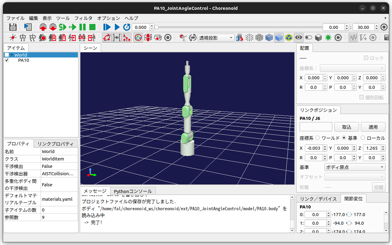
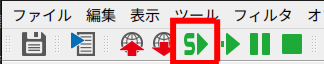
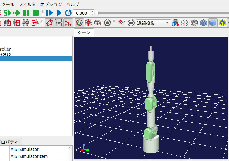
执行仿真
#点击屏幕上方的“开始仿真”按钮,启动仿真。
仿真启动后,如下图所示,每2.5秒机器人姿态都会变化。
另外,每次重新启动仿真时,机器人的角度模式应该会随机变化。
5. 结论
#这次虽然制作了用于驱动机器人各轴的SimpleController,但仍存在如下问题:
- 动作
- 机器人瞬间运动(速度趋于无限大),造成不现实的动作。希望机器人能平滑运动。
- 控制器
- 关节的最大值和最小值使用了硬编码。希望能通过Body文件的指针来获取。
- 由于轴数是以常量定义的,因此当机器人发生变化时无法使用相同的控制器。希望能使其更加通用。
- 仿真
- 仿真在经过10秒后仍未结束。希望结束后能自动退出。
下次将制作能解决上述问题的控制器。