Starting Robot Simulation with Choreonoid (Part 1)
Back to TopTo reach a broader audience, this article has been translated from Japanese.
You can find the original version here.
0. Introduction
#What is Choreonoid
#Choreonoid[1] is an open-source robot simulation software developed by the National Institute of Advanced Industrial Science and Technology (AIST). As of the latest version on January 10, 2025, it supports operation on the following operating systems:
- Ubuntu Linux
- Windows
In this article, we will use Ubuntu 22.04.
Originally, it was developed as a robot motion choreography tool, combining "Choreograph" (to choreograph) and "Humanoid" into its name.
Currently, development is continued by Choreonoid Inc., and the source code is publicly available on GitHub here[2].
The features of this simulator include:
- Usable as a dynamics simulator
- Smooth performance
- High extensibility through plugins
- Integration with ROS1 and ROS2 is possible
I used this simulator in my research during my student days, and its smooth operation was remarkable, especially when compared to the dynamics simulator Gazebo.
In this article, we will introduce the appeal of Choreonoid, along with usage methods and samples.
GitHub Link
#The code implemented in this article is shared here[3]. Please refer to it as needed.
1. Setting Up the Development Environment
#Creating a Working Directory
#Create the workspace directory to be used.
In this article, we will create a folder named Choreonoid_ws in the Home directory.
If you want to use a different folder name, please adjust accordingly.
$ mkdir -p ~/Choreonoid_ws
Cloning the Repository
#Clone the Choreonoid repository into the workspace directory.
$ cd ~/Choreonoid_ws
$ git clone git@github.com:choreonoid/choreonoid.git
Installing Related Tools
#Install the tools related to Choreonoid. Since there is a bash file in the repository to install everything at once, we'll use that.
The file to execute varies depending on your OS. Pay attention to the suffix of the file name.
This time, we will use the file corresponding to Ubuntu 22.04.
$ cd ~/Choreonoid_ws/choreonoid/misc/script
$ bash install-requisites-ubuntu-22.04.sh
Build
#Enter the cloned source code directory and build using CMake.
# Move to directory
$ cd ~/Choreonoid_ws/choreonoid

# Generate build system
$ cmake -S . -B build

# Execute build (parallel build)
$ cmake --build build --parallel 4
Installation
#In general applications, you might use make install to install to /usr/local and so on, but Choreonoid recommends leaving it generated within the home directory[4].
In this article, we will just add the path to the generated binary files.
Add the path to the executable files generated in the previous section to ~/.bashrc.
$ echo "export PATH=$PATH:~/Choreonoid_ws/choreonoid/build/bin" >> ~/.bashrc
After restarting the terminal to reflect the above changes, execute the following command to confirm that Choreonoid launches.
$ choreonoid
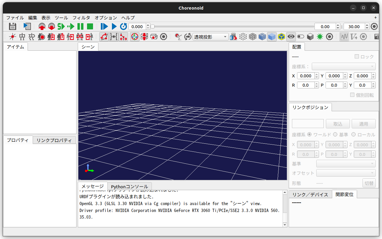
This completes the setup of the development environment.
2. Preparing the Project
#Creating a New Project Folder
#In this sample, we will use the model of Mitsubishi Heavy Industries' manipulator robot "PA-10"[5] (see figure below) that is publicly available within Choreonoid.
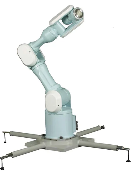 Mitsubishi Heavy Industries Electric General-Purpose Multi-Axis Manipulator PA-10
First, create a folder named PA10_JointAngleControl within the choreonoid/ext folder, which is the working directory.
This folder will contain project files and the controller's source code.
$ mkdir -p ~/Choreonoid_ws/choreonoid/ext/PA10_JointAngleControl
In this article, we will store files and so on within the existing choreonoid/ext folder.
You can create arbitrary folders within choreonoid, but for convenience, we will store them inside the ext folder.
From here on, we will create a subfolder for each controller and store the code and so on within it.
Copying the PA10 Model
#The PA10's model files are stored in the choreonoid/share/model/PA10 folder.
Copy the contents of this folder to the PA10_JointAngleControl we just created as the model folder.
$ cd ~/Choreonoid_ws/choreonoid
$ cp -r share/model/PA10 ext/PA10_JointAngleControl/model
The folder structure should look like this.
ext/
└── PA10_JointAngleControl/
    └── model/ (Copy of share/model/PA10)
Below is a part of the model/PA10.body file.
This file defines the robot model in YAML language, including each link's shape, characteristics, axis limits, and modeling files.
The Body file reference is here. Please refer to it as needed.
https://choreonoid.org/ja/manuals/latest/handling-models/modelfile/yaml-reference.html
format: ChoreonoidBody
formatVersion: 1.0
angleUnit: degree   # Angle unit
name: PA10

links:  # List of constituent links
  -
    name: BASE          # Link name (root link)
    jointType: fixed    # Fixed link
    mass: 3.04          # Mass [kg]
    centerOfMass: [ 0, 0, 0.075 ]   # Center of mass position
    inertia: [  # Moment of inertia
      1, 0, 0,
      0, 1, 0,
      0, 0, 1 ]
    elements:
      Visual: { resource: { uri: "parts/BASE.wrl" } }
      Collision:
        shape:
          rotation: [ 1, 0, 0, 90 ]
          translation: [ 0, 0, 0.1 ]
          geometry:
            type: Cylinder
            height: 0.2
            radius: 0.115
  -
    name: J1                    # Link name
    parent: BASE                # Parent link
    jointType: revolute         # Revolute link (joint)
    jointAxis: [ 0, 0, 1 ]      # Rotation axis
    jointId: 0                  # Joint ID
    translation: [ 0, 0, 0.2 ]  # Relative position from parent link
    rotation: [ 0, 0, 1, 0 ]    # Relative orientation from parent link
    jointRange: [ -177, 177 ]   # Limit angles
    jointVelocityRange: [ -180, 180 ] # Limit angular velocities
    rotorInertia: 3.0E-4        # Rotor moment of inertia
    mass: 9.78                  # Mass
    centerOfMass: [ 0, 0, 0.14818 ] # Center of mass position
    inertia: [
      1, 0, 0,
      0, 1, 0,
      0, 0, 1 ]
    elements:   # List of constituent elements of the link
      Visual: { resource: { uri: "parts/J1.wrl" } } # Specify model file
      Collision:  # Collision model
        elements: # Constituent elements
          -
            type: Shape
            rotation: [ 1, 0, 0, 90 ]
            translation: [ 0, 0, 0.01 ]
            geometry:
              type: Cylinder
              height: 0.02
              radius: 0.115
          -
            type: Transform
            translation: [ 0.085, 0, 0.09 ]
            elements: &J1_FRAME
              Shape:
                rotation: [ 1, 0, 0, 90 ]
                geometry:
                  type: Capsule
                  height: 0.062
                  radius: 0.058
          -
            type: Transform
            translation: [ -0.09, 0, 0.09 ]
            elements: *J1_FRAME
  -
    name: J2
    parent: J1
    jointType: revolute
    # (Continues)
List the upper and lower limit angles of each joint of PA10 in the table below.
| Joint Name | Lower Limit [deg] | Upper Limit [deg] |
|---|---|---|
| J1 | -177.0 | 177.0 |
| J2 | -94.0 | 94.0 |
| J3 | -174.0 | 174.0 |
| J4 | -137.0 | 137.0 |
| J5 | -255.0 | 255.0 |
| J6 | -165.0 | 165.0 |
| J7 | -255.0 | 255.0 |
| HAND_L | -0.030 | 0.030 |
| HAND_R | -0.030 | 0.030 |
Launching Choreonoid
#Now that we have built the Choreonoid development environment, let's prepare for the simulation.
First, launch Choreonoid from the terminal.
$ choreonoid
Adding the World
#Once Choreonoid is launched, we'll prepare for the simulation.
First, select "File" tab -> "New" -> "World", and set the world name to "World".
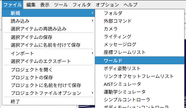
The world is the parent element of all elements.
Therefore, robots and simulations are created under the world.
By adding elements while selecting the parent element in the item tree, you can place them as child elements.
At this point, save the project file once.
Select "File" -> "Save Project As".
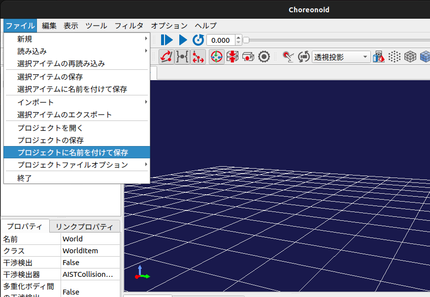
Create a "project" folder at the following location and save the file as "PA10_JointAngleControl".
ext/
└── PA10_JointAngleControl/
    ├── model/
    └── project/                          <--- Create new
        └── PA10_JointAngleControl.cnoid  <--- Saved file
Adding the Body File
#Add the body file as a child element to the "World".
While the "World" is selected,
select "File" -> "Load" -> "Body".
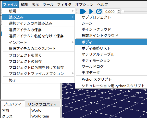
Select "PA10.body" from the "model" folder we copied earlier.
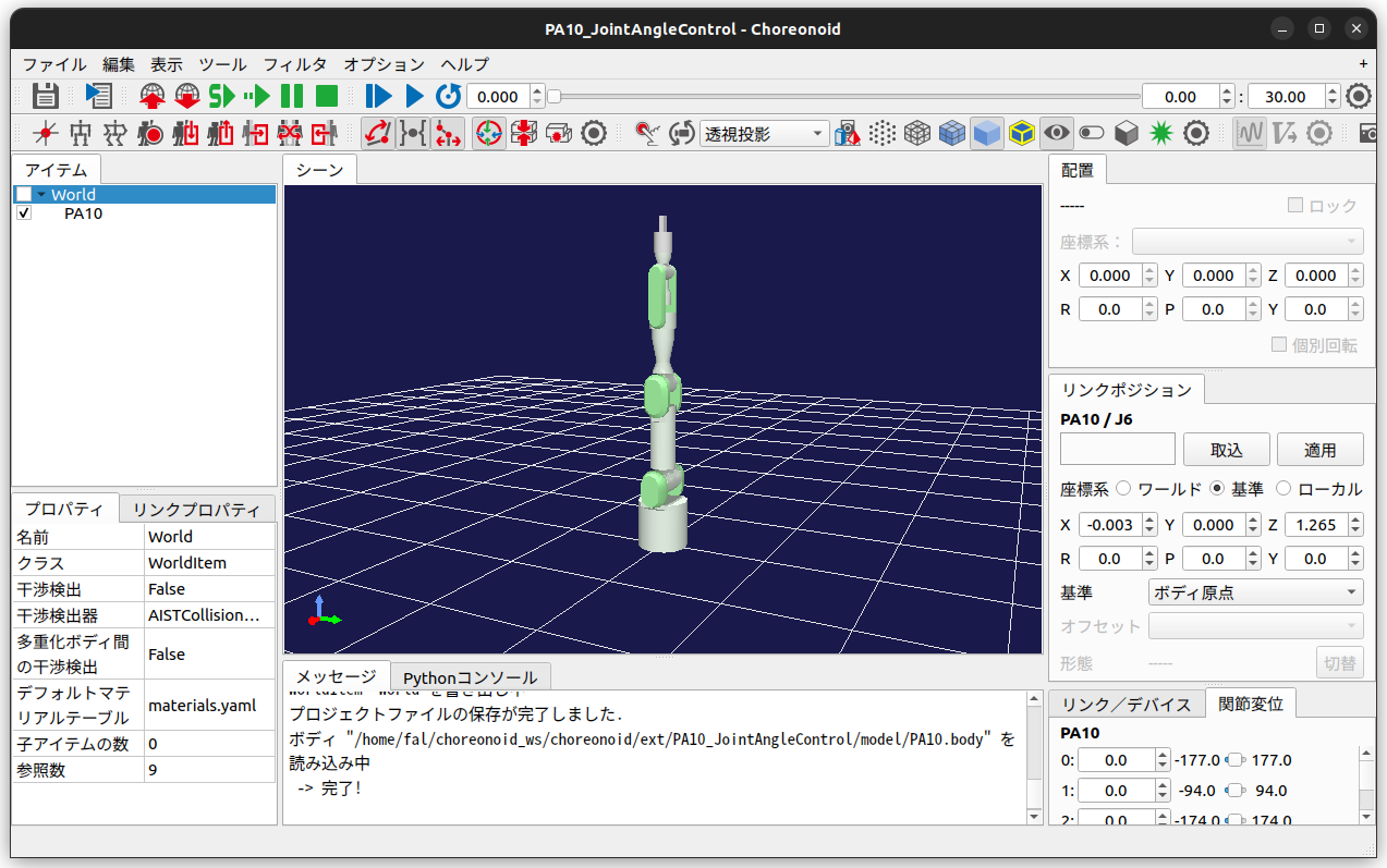
Once selected, the PA10 will appear on the screen.
Controller Settings
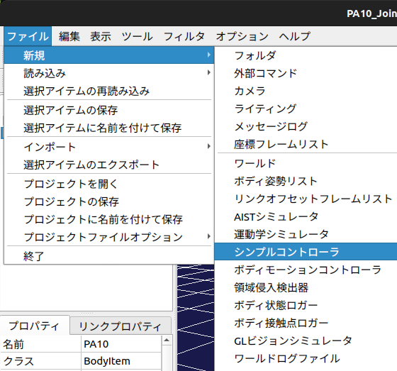
#Set the controller for the target model to be controlled.
First, with the PA10 (control target model) selected,
select "File" -> "New" -> "SimpleController".
Here, name the controller "JointAngleController".
We will later set the generated controller in this part.
Creating the Simulator
#The settings for the world and controller are now complete, but we will create an item for the simulation.
With the world selected,
select "File" -> "New" -> "AIST Simulator".
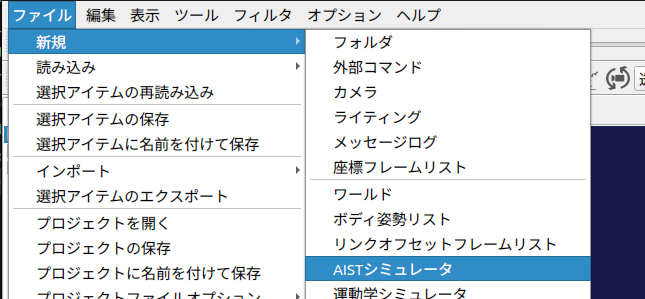
Name it "AISTSimulator".
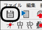
Saving the Project
#This completes the settings. Press the "Save" icon at the top left of the screen to save the current project configuration to a file.
This completes the preparation of the project. Let's close Choreonoid for now.
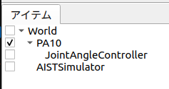
The final structure within the project will look like the figure below.
3. Creating a Controller that Outputs Target Joint Angles
#Types of Controllers Available in Choreonoid
#Choreonoid allows you to move robots using the following controllers:
- SimpleController
- Choreonoid's own lightweight controller
- Written in C++
- Python Controller
- Written in Python
- BodyIoRTC
- ROS Controller
- Plugin-based Controller
Creating Source Code Folder and Files
#We will create a controller to move the robot.
Create a source folder, source file, and CMakeLists.txt file inside the ext/PA10_JointAngleControl folder.
$ cd ~/Choreonoid_ws/choreonoid/ext/PA10_JointAngleControl
$ mkdir src
$ touch src/PA10_JointAngleController.cpp
$ touch CMakeLists.txt
Editing CMakeLists.txt
#Set up to build the created source file as a Choreonoid SimpleController.
choreonoid_add_simple_controller(PA10_JointAngleController src/PA10_JointAngleController.cpp)
Implementing the Controller
#Implement src/PA10_JointAngleController.cpp.
This time, we'll create a SimpleController as follows.
- For each axis of the robot, provide a randomly generated joint angle as the command value
- However, ensure that the values are within the joint limits
- Provide joint angles at the following time intervals
- t1 = 0.0 ~ 2.5 [s]
- t2 = 2.5 ~ 5.0 [s]
- t3 = 5.0 ~ 7.5 [s]
- t4 = 7.5 ~ 10.0 [s]
The code is as follows. (GitHub link is here)
#include <cnoid/SimpleController>
#include <random>

#pragma region Declaration

/// @brief Give joint angle to each joint of PA10
class PA10_JointAngleController : public cnoid::SimpleController
{
private:
    /// @brief The number of joints
    static const int jointNum = 9;

    /// @brief The number of patterns
    static const int patternNum = 4;

    /// @brief Joint limits of PA10 model
    const float JointLimit[jointNum] = {177.0, 94.0,  174.0, 137.0, 255.0,
                                        165.0, 255.0, 0.030, 0.030};

    /// @brief Patterns of joint angles
    float anglePattern[patternNum][jointNum];

    /// @brief Pointer for Body
    cnoid::BodyPtr ioBody;

    /// @brief Current simulation time [ms]
    double currentTime;

    /// @brief Simulation step time [ms]
    double timeStep;

    /// Methods
    float generateRandomFloat(float min, float max);
    float deg2rad(float deg);

public:
    /// Methods
    PA10_JointAngleController();
    virtual bool initialize(cnoid::SimpleControllerIO* io) override;
    virtual bool control() override;
};
CNOID_IMPLEMENT_SIMPLE_CONTROLLER_FACTORY(PA10_JointAngleController)

#pragma endregion

#pragma region Implementation

/// @brief Constructor (Not Implemented)
PA10_JointAngleController::PA10_JointAngleController() {}

/// @brief Executed once at SimpleController launched
/// @param io Pointer of SimpleControllerIO
/// @return Result of Initialization
bool PA10_JointAngleController::initialize(cnoid::SimpleControllerIO* io)
{
    // Obtain the pointer of Body
    ioBody = io->body();

    // Configure each joint
    for (int jointId = 0; jointId < jointNum; jointId++)
    {
        cnoid::Link* joint = ioBody->joint(jointId);

        // Set the way to control joint
        joint->setActuationMode(cnoid::Link::JointAngle);

        // Enable Input and Output for joint
        io->enableIO(joint);
    }

    // Initialize current time
    currentTime = 0.0;

    // Create joint angle patterns
    // Angle must be between joint limit.
    for (int patternId = 0; patternId < patternNum; patternId++)
    {
        for (int jointId = 0; jointId < jointNum; jointId++)
        {
            anglePattern[patternId][jointId] =
                generateRandomFloat(-JointLimit[jointId], JointLimit[jointId]);
        }
    }

    // Obtain timestep of simulation
    timeStep = io->timeStep();

    return true;
}

/// @brief Executed in every period
/// @return Result of Execution
bool PA10_JointAngleController::control()
{
    // Select pattern index according to current simulation time
    int currentPatternIndex;
    if (0 <= currentTime && currentTime < 2.5)
        currentPatternIndex = 0;
    else if (2.5 <= currentTime && currentTime < 5.0)
        currentPatternIndex = 1;
    else if (5.0 <= currentTime && currentTime < 7.5)
        currentPatternIndex = 2;
    else if (7.5 <= currentTime && currentTime < 10.0)
        currentPatternIndex = 3;
    else
        currentPatternIndex = 0;

    // Control angle of joint according to pattern index
    for (int jointId = 0; jointId < jointNum; jointId++)
    {
        //
        ioBody->joint(jointId)->q_target() = deg2rad(anglePattern[currentPatternIndex][jointId]);
    }

    // Calculate current time
    currentTime += timeStep;

    return true;
}

/// @brief Generate random float value
/// @param min Minimum
/// @param max Maximum
/// @return Generated value
float PA10_JointAngleController::generateRandomFloat(float min, float max)
{
    if (min > max)
    {
        throw std::invalid_argument("min must be less than or equal to max");
    }

    std::random_device rd;
    std::mt19937 gen(rd());
    std::uniform_real_distribution<float> dis(min, max);

    return dis(gen);
}

/// @brief Convert from degree to radian
/// @param angle Angle in degree
/// @return Angle in radian
float PA10_JointAngleController::deg2rad(float deg)
{
    return deg * M_PI / 180.0f;
}

#pragma endregion
Code Explanation
#We will explain important parts of the code.
initialize Method and control Method
#The PA10_JointAngleController class we created this time inherits from the cnoid::SimpleController class.
The cnoid::SimpleController class defines the following virtual functions.
By overriding them in the derived class, you can implement the desired processing.
| Method | Details |
|---|---|
configure(cnoid::SimpleControllerConfig* config) |
Executed when SimpleController is added to Body |
initialize(cnoid::SimpleControllerIO* io) |
Initialization process before starting simulation |
start() |
Executed when simulation starts |
control() |
Executed in every control cycle of the simulation |
stop() |
Executed when simulation stops |
unconfigure() |
Executed when controller is unloaded |
For details of the SimpleController class, please refer to the comments, etc., in
choreonoid/src/Body/SimpleController.h.
In the controller PA10_JointAngleController we created, we override two methods: initialize() and control().
In the initialize method:
- Setting input/output for each joint
- Creating joint angle patterns
- Obtaining simulation step time
In the control method:
- Updating the current time variable
currentTime - Switching patterns according to time
- Controlling joint angles according to the pattern
Giving Movement Commands to the Robot
#The flow to control the joint angles of the robot is as follows.
- Obtain a pointer to the Body in the
initializemethod
ioBody = io->body();
- Set each joint to be controlled by angle in the
initializemethod
// Configure each joint
for (int jointId = 0; jointId < jointNum; jointId++)
{
    cnoid::Link* joint = ioBody->joint(jointId);

    // Set the way to control joint
    joint->setActuationMode(cnoid::Link::JointAngle);

    // Enable Input and Output for joint
    io->enableIO(joint);
}
- In the
controlmethod, assign the target angle to the reference ofq_target
// Control angle of joint according to pattern index
    for (int jointId = 0; jointId < jointNum; jointId++)
    {
        //
        ioBody->joint(jointId)->q_target() = deg2rad(anglePattern[currentPatternIndex][jointId]);
    }
Building the Controller
#Add a description to build the SimpleController in CMakeLists.txt.
Specify the controller name as the first argument and the controller's source file as the second argument.
choreonoid_add_simple_controller(PA10_JointAngleController src/PA10_JointAngleController.cpp)
After editing, build as you did when building Choreonoid.
$ cd ~/Choreonoid_ws/choreonoid
$ cmake --build build --parallel 4
Once built, the controller file will be generated at the following location.
The controller is output as a .so file (shared library).
choreonoid/build/lib/choreonoid-2.2/simplecontroller/PA10_JointAngleController.so
We will later configure to use this file.
4. Executing the Simulation
#Launching Choreonoid
#Open Choreonoid again, which we closed earlier.
At this time, you can open the project by specifying the project file as the first argument of the command.
$ cd ~/Choreonoid_ws/choreonoid/ext/PA10_JointAngleControl
$ choreonoid project/PA10_JointAngleControl.cnoid
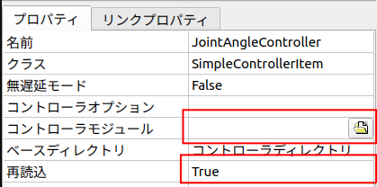
Setting the Controller
#Select the SimpleController item created in the "Controller Settings" section, and click "Controller Module" in the property section at the bottom left of the screen.
After clicking, click the icon that appears and specify the SimpleController file we generated earlier.
The location where it was generated is as follows.
choreonoid/build/lib/choreonoid-2.2/simplecontroller/PA10_JointAngleController.so
Also, change the "Reload" property to TRUE.
This saves you the trouble of resetting the SimpleController every time after building.
Once completed, save the project.
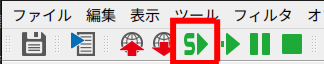
Running the Simulation
#Press the "Start Simulation" button at the top of the screen to start the simulation.
When the simulation starts, the robot's posture changes every 2.5 seconds as shown in the figure below.
Also, every time you restart the simulation, the robot's angle patterns should change randomly.
5. Summary
#In this article, we created a SimpleController to move each axis of the robot, but the following issues still remain.
- Motion
- The robot moves instantly (velocity is infinite), resulting in unrealistic movements. We want to move the robot smoothly.
- Controller
- The joint upper and lower limits are defined as magic numbers. We want to obtain them using pointers to the Body file.
- The number of axes is defined as a constant, so the same controller cannot be used when the robot changes. We want to make it usable in a general way.
- Simulation
- The simulation does not end even after 10 seconds have passed. We want it to end automatically when it's over.
Next time, we will create a controller that solves the above issues.
Reference Materials
#- Choreonoid Development Version Documentation
- Choreonoid Training RTF August 24-26, 2023 Choreonoid Training Materials