Algorithm 3 for Robot Manipulator Control
Back to TopTo reach a broader audience, this article has been translated from Japanese.
You can find the original version here.
Algorithm 3 for Robot Manipulator Control
#Takahiro Ishii, Engineering Solutions Division, Mamezou Co., Ltd.
1. Introduction
#At Mamezou Co., Ltd., we develop various robot technologies. While we often develop applied technologies using robots from other companies to meet client demands, we also develop industrial robots with 6-axis or 7-axis arms, commonly known as robot arms or manipulators, from scratch. Through this development, we generate various applied technologies and proposals. I would like to share the insights gained here with the readers. In this explanation, I will use a 6-axis industrial vertical articulated manipulator as an example to explain the various mechanisms for controlling it.
This time, I will explain the "singularity" problem, which inevitably arises when applying the previously explained trajectory generation processing algorithm to operate a manipulator or robot arm, including the theory. I will also introduce an example of a solution, known as "singularity avoidance."
2. Singularity of Robot Arm
#What is a Singularity?
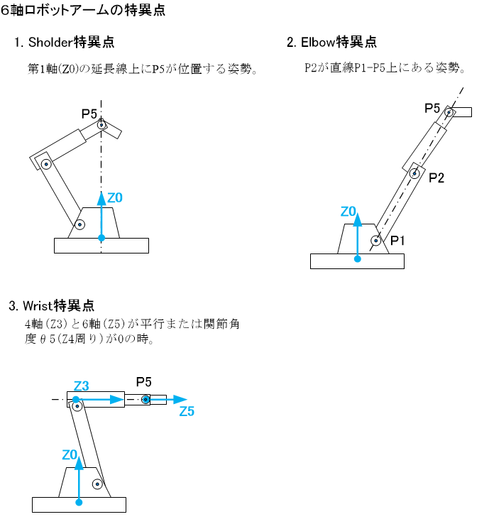
#As mentioned earlier, a robot arm can assume various postures by moving its six joint axes, changing the position and orientation (direction, angle) of the tool tip (TCP=Tool Center Point). However, when approaching or moving away from a specific posture, some parts of the arm may suddenly move rapidly, placing excessive loads on the servo motors or reducers, or causing significant vibrations. This specific posture is called a "singularity" of the robot arm. For the 6-axis industrial vertical articulated manipulator discussed in this article, the following three singularities are empirically known:
- Shoulder Singularity
- Elbow Singularity
- Wrist Singularity
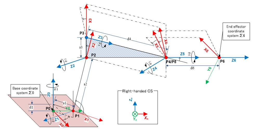
In the manipulator geometry shown below, (※Z-axis is the rotation axis at each joint)

These three singularities are defined as follows.
When the posture approaches these singularities, the arm's movement becomes problematic. For example, when moving slowly in the Z4 axis (Bn axis) direction (from back to front in this diagram) from the "3. Wrist Singularity" posture without changing the TCP's orientation, the arm between P3 and P4 may suddenly rotate around the Z3 axis (Rt axis). This rotation angle can reach nearly 90 degrees in an instant. Since the component beyond P3 is quite heavy, a sudden load is applied to the Rt axis servo motor, sometimes causing significant vibrations.
Mathematical Explanation of Singularity
#Let's mathematically explain what these singularities are.
First, let's revisit the Jacobian matrix and its usage introduced in the description of "forward/inverse kinematics calculation of velocity" explained earlier.
- : TCP position
- : Base coordinate system origin position
- "" is the cross product
- The T in the superscript denotes matrix transposition.
Using this Jacobian matrix, the translational and rotational velocities of the TCP can be calculated from the joint axis velocities as follows.
The inverse transformation can also be performed as follows.
Here,
- : 6-dimensional column vector representing the angular velocity of each joint axis
- : 6-dimensional column vector representing the TCP velocity
More specifically,
- : { } : Angular velocity at each joint axis
- : 3-dimensional translational velocity vector of TCP
- : 3-dimensional rotational velocity vector of TCP
Thus,
is represented.
The Jacobian matrix is determined by the instantaneous posture of the robot arm, but its inverse matrix may not be obtainable. In this case, regardless of the instantaneous movement of the TCP, the instantaneous rotation of the joint axis becomes indeterminate. When determining the elements of the inverse matrix, division by the determinant is necessary, so not being able to obtain means that the determinant is 0, i.e.,
This is precisely the posture that takes a singularity. On the other hand, in postures near a singularity, the determinant is close to but not zero. Therefore, can be obtained, but its elements can become enormous because they are divided by the minute . Therefore, when calculating
even if the movement of the TCP is small, the elements of the change in joint angle can become enormous. This is why some parts of the arm exhibit abnormal behavior near singularities.
Singularity Avoidance
#Main Avoidance Methods
#As mentioned above, there are problems with movement near singularities, so methods have been devised to somehow avoid these singularities. The main methods are as follows:
- Slightly change the original trajectory (TCP path or orientation) when approaching a singularity.
- Rapidly reduce the speed of all motors uniformly when approaching a singularity without changing the original trajectory.
In method 1, the operation proceeds according to the planned time, but accuracy is compromised due to deviation from the original trajectory. In method 2, the planned trajectory is accurately followed, but the operation is significantly delayed compared to the initially planned time.
Since industrial robot manipulators are often used in production sites such as factories, the issue of time-saving is important. Also, if careful programming is done to avoid singularities in important trajectories requiring accuracy, and only become singularities in simple tool movement scenes, method 1 is acceptable. Therefore, this article explains a method of singularity avoidance using "singularity low-sensitivity motion decomposition," an example of method 1 that was actually adopted (see Reference 1).
Singularity Avoidance by Singularity Low-Sensitivity Motion Decomposition
#Overview of the Method
Reference 1 introduces a method of introducing a low-sensitivity motion decomposition matrix to slightly change the original trajectory (TCP path or orientation) when approaching a singularity. The way of changing (sensitivity) can be finely adjusted with parameters. The specific calculation method when applying this method to a 6-axis manipulator is explained. The reference document generally mentions any multi-joint manipulator, and is not necessarily a square matrix, so it is replaced with a generalized inverse matrix (pseudo matrix) for discussion. However, since and are square matrices in this article, they are used without replacement.
The outline of this method is as follows:
From the condition to minimize the error between the exact TCP position and orientation, a low-sensitivity motion decomposition matrix for performing low-sensitivity motion decomposition can be derived. By using this instead of during trajectory generation, it is possible to operate in such a way that sacrifices the "orientation" accuracy of the TCP while maintaining the "position" accuracy of the TCP near singularities. As a result, singularities can be successfully avoided. At this time, no joint axis undergoes unexpected rapid acceleration and operates smoothly. Incidentally, completely matches when moving away from the vicinity of a singularity.
Low-Sensitivity Motion Decomposition Matrix
The derivation is omitted, and the definition of the low-sensitivity motion decomposition matrix is shown below.
where
Furthermore,
- : 6x6 diagonal matrix determining the sensitivity of joint axis motion
- Default value:
- : 6x6 diagonal matrix determining the sensitivity of TCP motion
- Default value:
- Here,
- : Maximum translational speed of TCP in design specifications
- : Maximum rotational speed of TCP in design specifications
- : Nakamura's index indicating whether the robot arm's posture is close to a singularity
- at a singularity, asymptotically approaching 0 when away from a singularity
- Defined as follows
Here, and are control adjustment values determined by the following guidelines.
-
- Adjustable between 0.0 and 1.0. Default value: 0.01
- Increasing it reduces the sensitivity of to TCP movement near singularities. While it alleviates sudden acceleration of some axes, it tends to deviate from the target trajectory.
- Decreasing it improves adherence to the target trajectory.
-
- Boundary reference value separating singular and non-singular regions
- Calculated as . It is good to use the Jacobian matrix calculated for the posture when is changed to about 10° to 30° from the Wrist singularity posture (=0°).
Trajectory Generation Algorithm Using
The specific method for trajectory generation that can avoid singularities using is explained.
First, for a posture composed of a certain set of joint angles , the calculated is expressed as a function
Also, let be the time, and
- : Time series of joint angles to be taken
- : Time series of 6-dimensional column vector representing TCP velocity
- : Small time interval
Then, theoretically, the recurrence formula including the following integral
can be calculated to output a set of joint angles that can generate a trajectory capable of avoiding singularities in real-time. However, in practice, it is difficult to accurately calculate . Even if the original velocity calculated from the original trajectory (trajectory calculated by the previously described trajectory generation method) is considered as and the above integral is performed to obtain a new , it will deviate more and more from the original course each time it passes near a singularity.
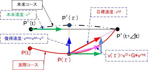
For example, as shown in the diagram below, when actually at the point on the course, if the TCP moves with the original velocity that should be taken on the original course, it will continue to move off the course, so it will be further away from the planned target point at the next time point. To avoid this, it is necessary to move while deviating by the recovery velocity to return exactly to the planned course. Note that is the difference between the target velocity for moving accurately to the target point from the current point and the original velocity .
Based on the above concept, the following calculations using feedback control are performed to ensure that the original course can always be returned to even if deviated.
First, define as follows.
Here, is the time between [ to ], and if is the operation to find the TCP coordinates from the joint angles, that is, the forward kinematics operation, then
In this, is the velocity when the TCP is moving along the original course, is the target velocity for the TCP to move straight to the next original position/orientation, and is the recovery velocity for the TCP to approach the original course. Also,
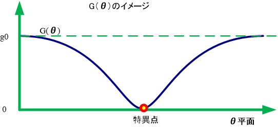
- is the Gain value for returning to the target TCP trajectory (0.0 to 1.0). Near singularities, G approaches 0.

- is set to 2.0.
- is the recovery coefficient. Default value: 0.0001
- is the same as the sample time for trajectory generation.
Using the above, the previous integral can be calculated. However, in practice, the following approximation, which simplifies this integral, can be used. This allows the output of joint angle sets that can return to the original course in real-time.
Note that when passing through a singularity, the course may slightly shift sideways even if a linear course is expected. In this case, the course deviation can be adjusted by adjusting the values of , , or , . Also, note that if the value of is large, the course may oscillate.
3. Conclusion
#I explained what singularities of robot arms are and how to avoid singularities in 6-axis robot arms. In actual system implementation, parameter adjustments are made by operating these on actual machines. Also, in practice, functions such as singularity avoidance during JOG operation using a pendant and singularity detection alarm functions are also required separately. However, these can be implemented by applying the theory in this article.
References
#- Hitoshi Nakamura, Hidero Hanabusa, ","Singularity Low-Sensitivity Motion Decomposition for Joint-Type Robot Arms," Transactions of the Society of Instrument and Control Engineers, Vol. 20, No. 5 (May 1984)
- Shigeki Toyama (Author), "Robotics (Mechatronics Textbook Series)," Corona Publishing (1994)


