Trying Out IoT (Part 14: Organic EL Display (OLED) SSD1306 Edition)
Back to TopTo reach a broader audience, this article has been translated from Japanese.
You can find the original version here.
This article is the 18th day article of the Mamezou Developer Site Advent Calendar 2023.
Last time, we introduced the temperature and humidity sensor module "DHT11".
This time, we introduce the "Organic EL Display (OLED) SSD1306" used in IoT devices.
Organic EL Display (OLED) SSD1306
#Last time, we transferred the temperature and humidity information obtained from the DHT11 to the PC via serial communication and checked the COM port information with the serial monitor.
However, it is cumbersome to launch the serial monitor each time to check the results.
So this time, we will display the temperature and humidity on the "Organic EL Display (OLED)".
(OLED stands for "organic light-emitting diode".)
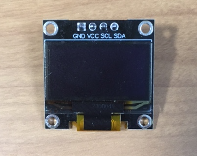
The OLED model we are using this time is the "small and inexpensive" SSD1306.
We chose a 0.96-inch size (128 pixels wide x 64 pixels high).
There are two types of communication methods: I2C (IIC) and SPI, but we are using the I2C communication type, which operates with 4 pins.
Table:
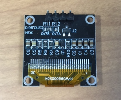
Back:
They are sold for about 500 yen each on Amazon.
They are even cheaper on AliExpress. (I bought one for about 160 yen on AliExpress)
The display colors available are "Blue", "White", and "Blue+Yellow".
I chose "White" according to my preference.
Development Environment "Platform IO"
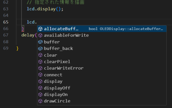
#Until now, I used the "Arduino IDE" for software development with ESP32 and Arduino, but I found it painful that code completion was not available during program implementation.
I wanted to write code in VSC (Visual Studio Code) that I use regularly, and then I learned about the development environment called "Platform IO".
This Platform IO (hereinafter referred to as PIO) IDE can be used as a plugin for VSC.
I immediately searched for "PlatformIO IDE" in VSC's extensions and installed it.
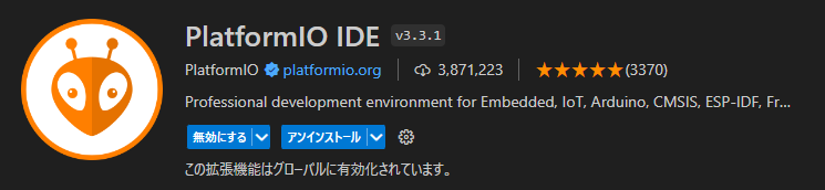
You can also install it from the following URL.
Once the installation is complete, the following icon is added to VSC.
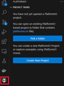
Is this icon an ant or an alien?
I wasn't sure, so I asked ChatGPT.
Here is the answer.
Development Target Microcontroller Board "ESP32"
#The microcontroller board we are developing is the "ESP32 DevkitC V4" (hereinafter referred to as ESP32).
We used it before.
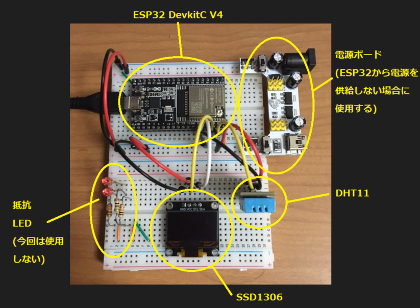
This time, I would like to place the ESP32 on a breadboard along with the DHT11 and SSD1306.
However, there was one problem...
Here is an image of the ESP32 inserted into the breadboard.
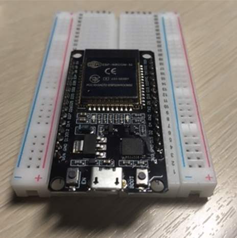
Hmm??? Something is strange, isn't it?
Everyone, have you noticed...?
Actually, the pin width of this ESP32 is wide, and it does not fit well on a 5-pin breadboard on one side.
You can barely pull out the pins with jumper pins on one side, but there is no room to insert jumper pins on the other side.
There is barely one row of space on one side.
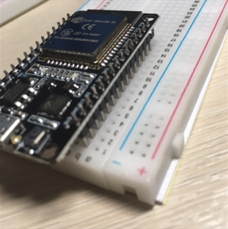
The other side is packed up to the power line.
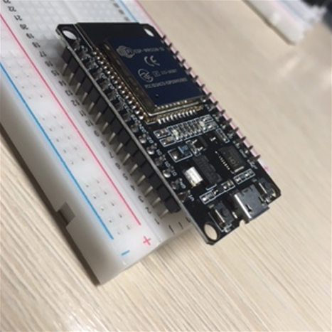
In the end, I only activated one side of the ESP32, pulled out the power from the 5V pin with a jumper wire, and forcibly placed it on the breadboard.
(I realized that if I had multiple breadboards, I could have spanned the ESP32 across two breadboards, but I realized this after the trial and error was over...)
Many people seem to have encountered this problem.
There are even brave souls who have cut the breadboard in half.
Also, a breadboard with 6 pins on one side seems to be on sale.
Connecting the Devices
#Now, let's connect the DHT11 and SSD1306 to the ESP32.
For the DHT11, we are using pin 23 this time, which is different from the last time we connected it to the ESP32 (because we can only use one side of the ESP32)
| ESP32 | DHT11 |
|---|---|
| 5V | + |
| 23rd | OUT |
| GND | - |
For the SSD1306, we were able to use the default SDA (21st) and SCL (22nd) as they were.
| ESP32 | SSD1306 |
|---|---|
| GND | GND |
| 5V | VCC |
| 21st | SDA |
| 22nd | SCL |
Creating a Development Project with Platform IO IDE
#Sorry for the long introduction.
Now, let's start programming with the Platform IO IDE (hereinafter referred to as PIO IDE).
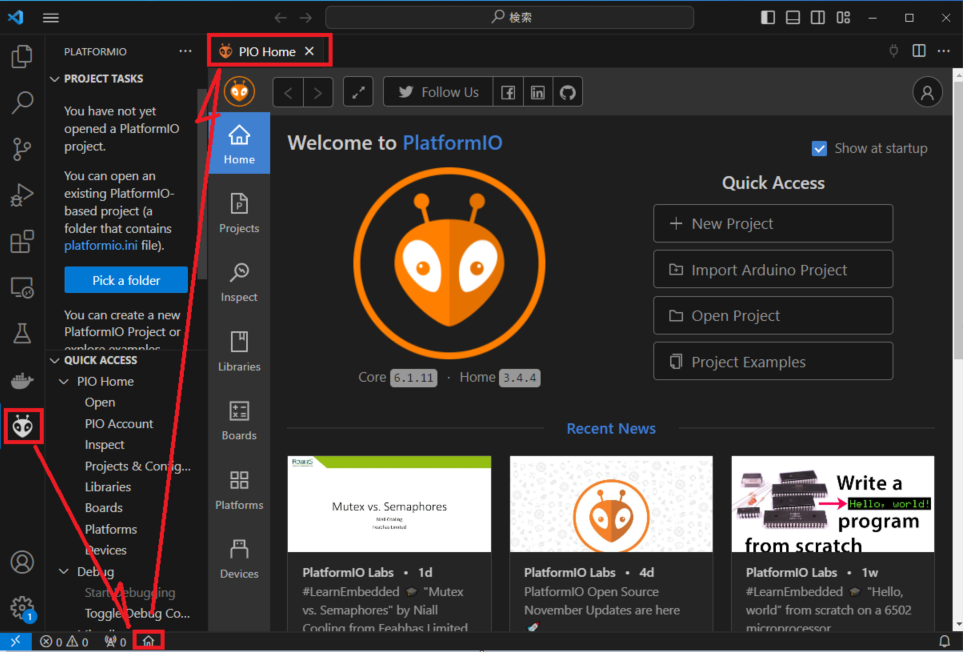
Click the PIO IDE icon, then click the "HOME" icon at the bottom bar of VSC. The "PIO HOME" screen will be displayed.
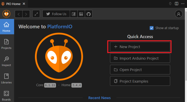
Click "New Project".
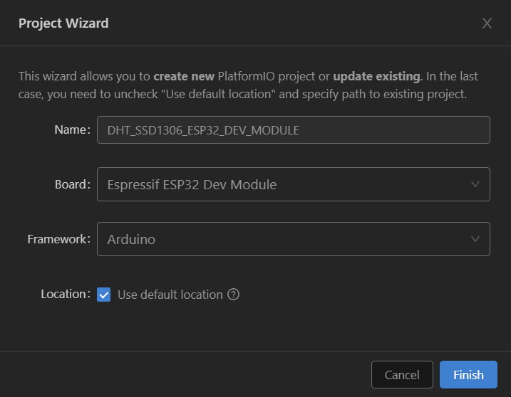
Set up the Project Wizard as follows and press the "Finish" button.
- Name (free description): Project name (set any project name that represents the content of the implementation)
- Board (selection): This time, we selected "Espressif ESP32 Dev Module".
- Framework (selection): We selected "Arduino". (You can also select Espidf, but we chose Arduino because we want to program Arduino-compatible this time)
- Location: Leave "Use default location" checked.
The project is created.
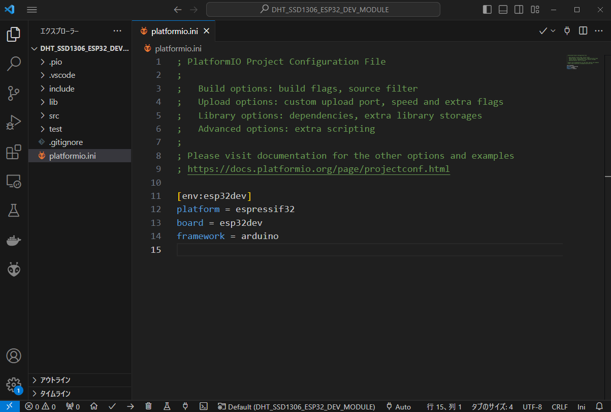
Let's check the contents of "platformio.ini".
This INI file contains the necessary information for the project.
If it is set as follows, the environment setting is successful.
However, as it is, we cannot use the DHT11 or SSD1306, so we will add libraries.
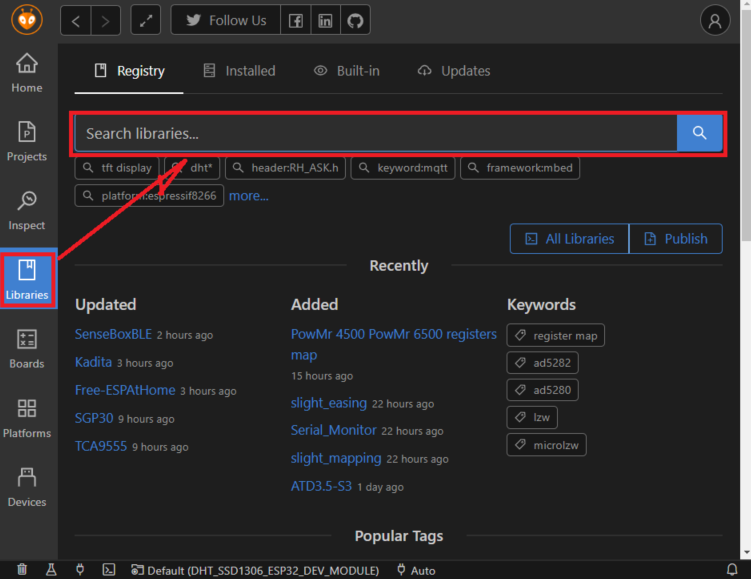
Press the HOME button to display "PIO Home" and press the "Libraries" button. Then search for the necessary libraries from "Search libraries" and install them.
The necessary libraries are the following three:
DHT11 related:
- DHT sensor library by Adafruit
- Adafruit Unified Sensor by Adafruit
SSD1306 related:
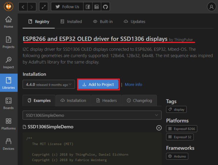
- ESP8266 and ESP32 OLED driver for SSD1306 displays by ThingPulse
Search for the libraries and add them to the project using the "Add to Project" button.
(The following is an example of selecting the SSD1306 library)
When you add a library, the library information is added to "platformio.ini".
[env:esp32dev]
platform = espressif32
board = esp32dev
framework = arduino
lib_deps =
	thingpulse/ESP8266 and ESP32 OLED driver for SSD1306 displays@^4.4.0
	adafruit/Adafruit Unified Sensor@^1.1.14
	adafruit/DHT sensor library@^1.4.6
The programming environment is now ready.
Programming
#Now, let's write a program to retrieve temperature and humidity information from the DHT11 and display the data on the OLED.
Since we have selected Arduino as the framework, the flow will be to write code within the two functions "void setup()" and "void loop()".
The final program is as follows.
#include <Arduino.h>
#include "DHT.h"
#include "SSD1306Wire.h" // legacy: #include "SSD1306.h"
// DHT11
#define DHTPIN 23 // Specify pin 23
#define DHTTYPE DHT11 // for DHT 11
DHT dht(DHTPIN, DHTTYPE);
// SSD1306
// ADDRESS I2C address 0x3C
// SDA Data line GPIO 21
// SCL Clock line GPIO 22
SSD1306Wire lcd(0x3c, SDA, SCL);
void setup() {
dht.begin(); // Initialize DHT
lcd.init(); // Initialize the display
lcd.setFont(ArialMT_Plain_16); // Set the font
lcd.flipScreenVertically(); // Flip the display (depending on how the LCD is mounted on the board)
}
void loop() {
float t = dht.readTemperature(); // Get temperature
float h = dht.readHumidity(); // Get humidity
lcd.clear(); // Clear display
if( isnan(t) || isnan(h) ) {
// Sensor error
lcd.drawString(0, 0, "DHT Error.");
lcd.display();
}
else {
// Temperature =================================
char buf_t[32];
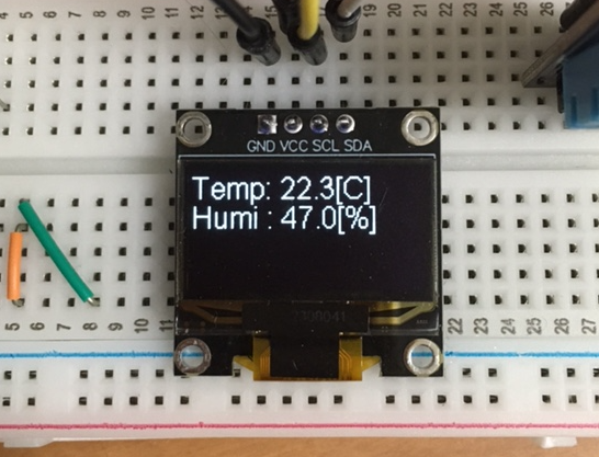
sprintf(buf_t, "Temp: %.1f[C]", t);
// Display at position (0,0)
lcd.drawString(0, 0, buf_t);
// Humidity =================================
char buf_h[32];
sprintf(buf_h, "Humi : %.1f[%%]", h);
// Display at position (0,16)
lcd.drawString(0, 16, buf_h);
// Draw the specified information
lcd.display();
}
delay(100);
}
Let's explain each part of the program.
First, the header declarations.
#include <Arduino.h>
#include "DHT.h"
#include "SSD1306Wire.h"            // legacy: #include "SSD1306.h"
Since we have selected Arduino as the framework, we add the first line "#include <Arduino.h>".
This is like a promise.
Then we add the header for the DHT library and the SSD1306 library.
(There are examples where "SSD1306.h" is selected in past information, but the latest seems to be "SSD1306Wire.h".)
Next is the DHT11 setting.
#define DHTPIN 23
#define DHTTYPE DHT11
DHT dht(DHTPIN, DHTTYPE);
Set the OUT pin to pin 23 and specify the DHT type as "DHT11".
Create a DHT object "dht".
SSD1306 setting.
SSD1306Wire lcd(0x3c, SDA, SCL);
SSD1306 takes the I2C address (=0x3c), SDA pin number (=21), and SCL pin number (=22) as arguments.
SDA and SCL are defined in "pins_arduino.h"() as follows.
Being able to easily refer to declarations and definitions like this is a unique feature of VSC.
static const uint8_t SDA = 21;
static const uint8_t SCL = 22;
As a side note, I will explain how to distinguish I2C addresses.
The I2C address set when I purchased the SSD1306 this time was "0x3C".
You can tell this by the jumper part on the back of the OLED being connected to the 0x78 side.
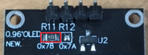
The jumpered part is probably a chip resistor.
(The characters are small, but it reads "472", so 47×10^2=4700[Ω]=4.7[kΩ], right?)
The I2C address changes depending on the position of this jumper.
The correspondence seems to be as follows.
| Jumper position | I2C address |
|---|---|
| 0x78 | 0x3C |
| 0x7A | 0x3D |
Contents of void setup().
  dht.begin();                      // Initialize DHT

  lcd.init();                       // Initialize the display
  lcd.setFont(ArialMT_Plain_16);    // Set the font
  lcd.flipScreenVertically();       // Flip the display (depending on how the LCD is mounted on the board)
First, initialize the DHT11.
Next, initialize the display (OLED).
We selected the font "ArialMT_Plain_16". (There seem to be other options, but I haven't looked into them in detail)
Also, since the default display direction was opposite to the silk printing direction, I flipped the display (set the pin position to the top of the display).
Now for the void loop() part.
This is a bit long, so I'll split it up.
  float t = dht.readTemperature();  // Get temperature
  float h = dht.readHumidity();     // Get humidity
Retrieve temperature and humidity information from the DHT11.
lcd.clear(); // Clear display
Clear the display once.
  if( isnan(t) || isnan(h) ) {
    // Sensor error
    lcd.drawString(0, 0, "DHT Error.");
    lcd.display();
  }
If data cannot be obtained from the DHT11, display the text "DHT Error" on the display.
    // Temperature =================================
    char buf_t[32];
    sprintf(buf_t, "Temp: %.1f[C]", t);

    // Display at position (0,0)
    lcd.drawString(0, 0, buf_t);
Display the temperature information at position "0,0".
    // Humidity =================================
    char buf_h[32];
    sprintf(buf_h, "Humi : %.1f[%%]", h);

    // Display at position (0,16)
    lcd.drawString(0, 16, buf_h);
Display the humidity information at position "0,16".
(The font size is 16 pixels, so it is set at a position shifted by 16 pixels.)
    // Draw the specified information
    lcd.display();
Display the specified information on the display.
delay(100);
Well, it's like a charm.
Writing the Program to ESP32
#Build the program with PIO IDE and upload it to ESP32.
It seems to automatically detect the COM port when uploading.

First, press "Build" to confirm that the program builds correctly.
Next, connect the ESP32 to the COM port and press "Upload" to upload the program to the ESP32.
If the program is uploaded and the temperature and humidity are displayed on the OLED, it is successful.
Before using the OLED, I used to display it on another LCD (the IoT device in the image below is "1602A"), but I thought the OLED was smaller and easier to handle.
(OLED does not require a backlight, so it should consume less power)
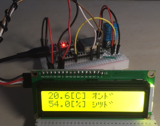
(1602A is definitely big...)
Bonus (Arduino UNO Edition)
#I also tried programming for Arduino UNO (hereinafter referred to as Arduino) using PIO IDE.
The completed program is as follows.
#include <Arduino.h>
#include "DHT.h"
#include <Wire.h>
#include <Adafruit_GFX.h>
#include <Adafruit_SSD1306.h>

#define SCREEN_WIDTH 128 // OLED display width, in pixels
#define SCREEN_HEIGHT 64 // OLED display height, in pixels

// On an arduino UNO:       A4(SDA), A5(SCL)
#define OLED_RESET     -1 // Reset pin # (or -1 if sharing Arduino reset pin)
#define SCREEN_ADDRESS 0x3C ///< See datasheet for Address;
Adafruit_SSD1306 display(SCREEN_WIDTH, SCREEN_HEIGHT, &Wire, OLED_RESET);

#define DHTPIN 14 // Use A0 pin
#define DHTTYPE DHT11
DHT dht( DHTPIN, DHTTYPE );

void setup() {
  dht.begin();

  // SSD1306_SWITCHCAPVCC = generate display voltage from 3.3V internally
  if(!display.begin(SSD1306_SWITCHCAPVCC, SCREEN_ADDRESS)) {
    Serial.println(F("SSD1306 allocation failed"));
    for(;;); // Don't proceed,,loop forever
  }

  // Show initial display buffer contents on the screen --
  // the library initializes this with an Adafruit splash screen.
  display.display();
  delay(2000); // Pause for 2 seconds

  // Clear the buffer
  display.clearDisplay();
  display.setTextColor(SSD1306_WHITE);
  display.setTextSize(2); // Draw 2X-scale text
}

void loop() {

  float t = dht.readTemperature();  // Temperature
  float h = dht.readHumidity();     // Humidity

  display.clearDisplay();

  if( isnan(t) || isnan(h) ) {
    display.setCursor(0, 0);
    display.println("Failed to read DHT");
  }
  else {
    // Temperature =================================
    char strTemperature[32];
    dtostrf(t,4,1,strTemperature);
    char buf_t[32];
    sprintf(buf_t, "T: %s(C)", strTemperature);

    // LCD
    display.setCursor(0, 0);
    display.println(buf_t);

    // Humidity =================================
    char strHumidity[32];
    dtostrf(h,4,1,strHumidity);
    char buf_h[32];
    sprintf(buf_h, "H: %s(%%)", strHumidity);

    // LCD
    display.setCursor(0, 16);
    display.println(buf_h);

  }
  display.display();

  delay(100);
}
I assembled this program thinking it would work fine since it worked well on the ESP32, but I encountered several issues.
The SSD1306 library I used for the ESP32 was specifically for "ESP8266 and ESP32", and it did not work with Arduino.
I had to switch to a library that could be used with Arduino.
In the Platform IO INI file, I specified the libraries as follows:
[env:uno]
platform = atmelavr
board = uno
framework = arduino
lib_deps =
	adafruit/Adafruit Unified Sensor@^1.1.14
	adafruit/DHT sensor library@^1.4.6
	adafruit/Adafruit SSD1306@^2.5.9
(All libraries are made by Adafruit, which is aesthetically pleasing, I guess.)
However, the biggest stumbling block was
"Arduino does not support sprintf with floating point format specifications."
I never imagined that 'sprintf' would be the cause, so I was quite puzzled as to why the data was not being retrieved.
It wasn't because of using PIO, as the same phenomenon occurred with the Arduino IDE, so it must be a limitation of Arduino itself.
I was helped by the information found at this URL.
I used a dedicated function called 'dtostrf', and although it's a bit rough, I managed with the following implementation:
    char strTemperature[32];
    dtostrf(t,4,1,strTemperature);
    char buf_t[32];
    sprintf(buf_t, "T: %s(C)", strTemperature);
There were various issues, but I was able to get the OLED working on Arduino as well.
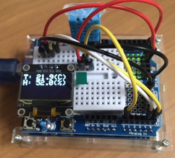
(I placed an expansion board + breadboard on top of the Arduino, and mounted the DHT11 and SSD1306 on it.)
Conclusion
#In this session, we used the "Organic EL Display (OLED) SSD1306" to display data from the DHT11.
This saves the effort of outputting data to the COM port.
There were slight differences between ESP32 and Arduino, which made things a bit challenging.
Using code completion with VSC + PIO IDE is very convenient.
I have compiled tutorials and practical techniques related to IoT.
I hope this will be helpful for your IoT applications.