Introduction to Calibration Patterns Available in OpenCV
Back to TopTo reach a broader audience, this article has been translated from Japanese.
You can find the original version here.
Introduction
#This time, I will introduce the planar patterns for camera calibration available in the image processing library OpenCV.
To utilize cameras in OpenCV, calibration work is sometimes necessary. Camera calibration can correct for image distortion caused by lenses, measure the positional relationship between robots and cameras, and construct stereo cameras. However, to perform calibration, a flat pattern with a dedicated marker printed on it is necessary. OpenCV comes standard with several calibration patterns with detection capabilities, which I will introduce along with their features.
About Camera Calibration
#In camera calibration, the following three elements are usually measured:
- Internal parameters: the optical center and focal length of the camera
- External parameters: the position and attitude of the camera
- Lens distortion: distortion of the lens
Detailed explanations of each element are available online, so I will omit them here.
Typical uses for each element include correcting image distortion caused by lenses, which requires internal parameters and lens distortion. To convert the work posture detected by the camera from the camera coordinate system to the robot coordinate system, external parameters are necessary.
The elements of the calibration pattern used differ depending on the elements you want to measure. Internal parameters and lens distortion measurements use the grid points of the calibration pattern.

On the other hand, the measurement of external parameters mainly uses the attitude of the calibration pattern.
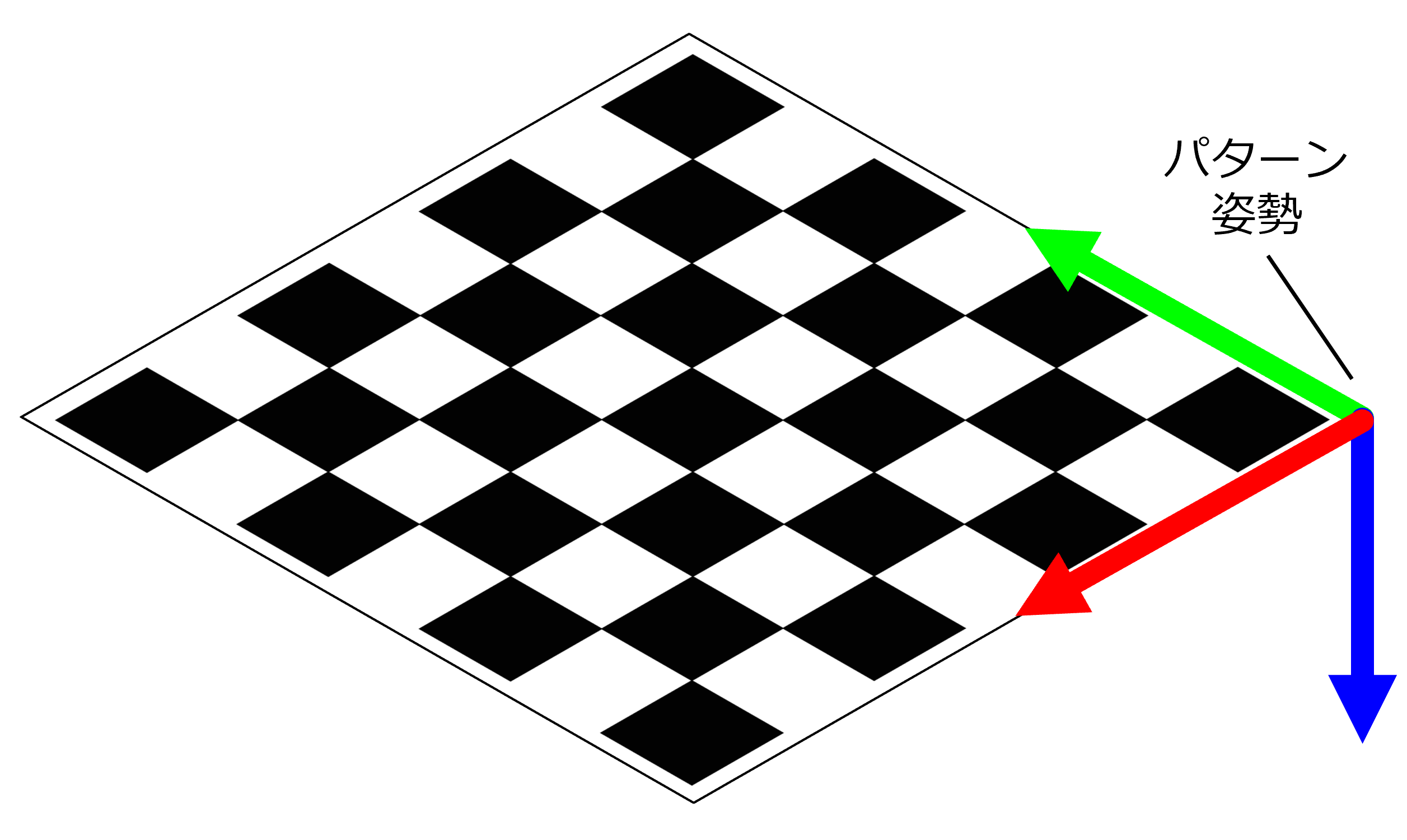
You need to select the appropriate calibration pattern depending on what you want to measure.
Types of Patterns
#The following are four typical patterns available in OpenCV:
- CheckerBoard
- CircleGrid
- AsymmetryCircleGrid
- ChArUco
Each pattern can be generated in any size at calib.io.
CheckerBoard
#A calibration pattern with a grid pattern.
Also called ChessBoard.
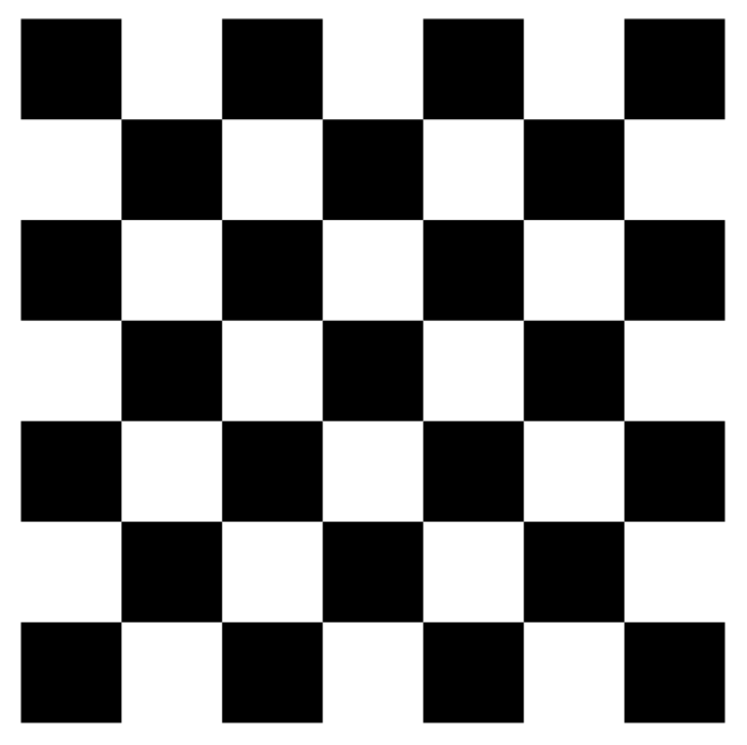
Pattern Specifications
- Rows: 7
- Columns: 7
- Checker Width[mm]: 28
This is the most basic and well-known calibration pattern. The inner grid points are used for calibration.
The detection results of the pattern are as follows:
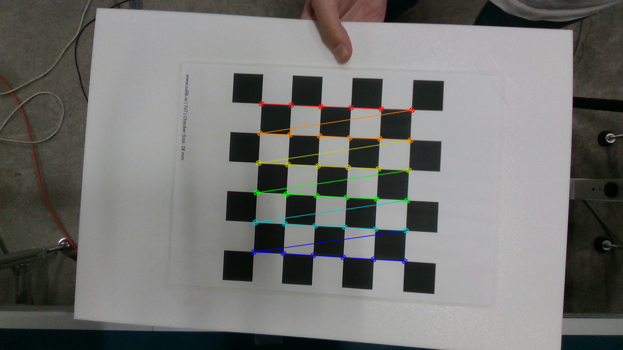
In OpenCV, detected grid points can be colored and drawn like this, making it visually easy to understand.
When the pattern is rotated around the camera's optical axis, the origin and orientation of the pattern coordinates cannot be uniquely determined.
Therefore, it cannot be used for measuring external parameters.

The X-axis is red, the Y-axis is green, and the Z-axis is blue.
CircleGrid
#A calibration pattern with dot markers arranged in a grid.

Pattern Specifications
- Rows: 7
- Columns: 7
- Circle Spacing[mm]: 28
- Diameter[mm]: 16
The centroids of each dot are used as grid points for calibration.
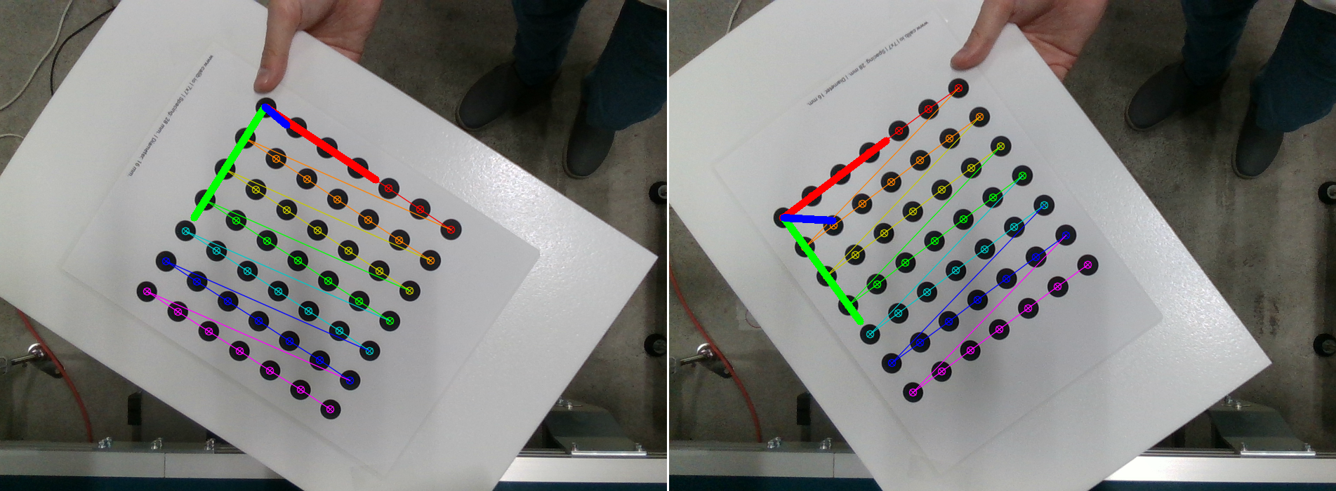
The detection results of the pattern are as follows:
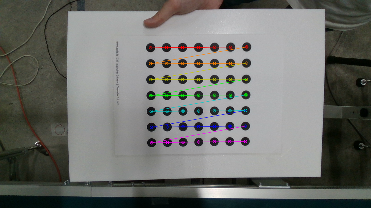
When the pattern is tilted relative to the camera, the shape of the circle dots becomes elliptical, but the position of each dot's centroid hardly changes.
Therefore, it is said that CircleGrid can detect more accurately than ChessBoard.
This pattern also cannot uniquely determine the pattern attitude when rotated around the camera's optical axis, so it cannot be used for measuring external parameters.
Asymmetry-CircleGrid
#A calibration pattern with dot markers arranged in a slanted grid.

Pattern Specifications
- Rows: 4
- Columns: 9
- Circle Spacing[mm]: 28
- Diameter[mm]: 16
The difference from CircleGrid is that the pattern is asymmetrical, so the pattern attitude can be uniquely determined.
Therefore, it can be used for measuring internal parameters, external parameters, and lens distortion.
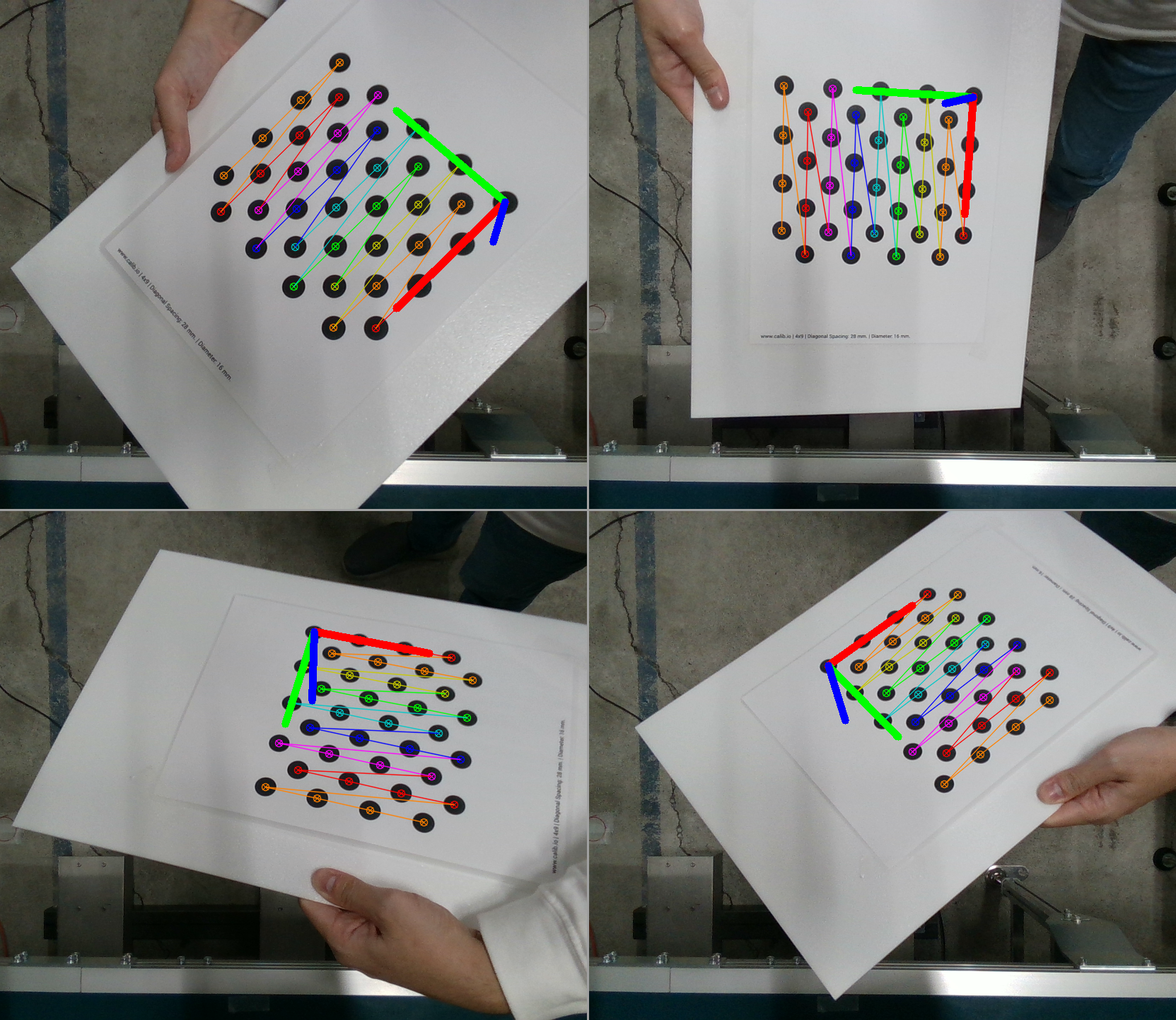
In the example above, the number of columns is odd at 9, but care must be taken because if the number of columns is even, it becomes point-symmetric and the pattern attitude cannot be uniquely determined.

ChArUco
#A calibration pattern that combines CheckerBoard and ArUco markers.
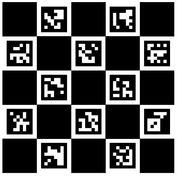
Pattern Specifications
- Rows: 5
- Columns: 5
- Checker Width[mm]: 40
- Dictionary: DICT_6X6
It can also be used as a CheckerBoard, but its main feature is the scattered ArUco markers.
Unlike a regular CheckerBoard, the pattern attitude in ChArUco is uniquely determined by the ArUco markers.
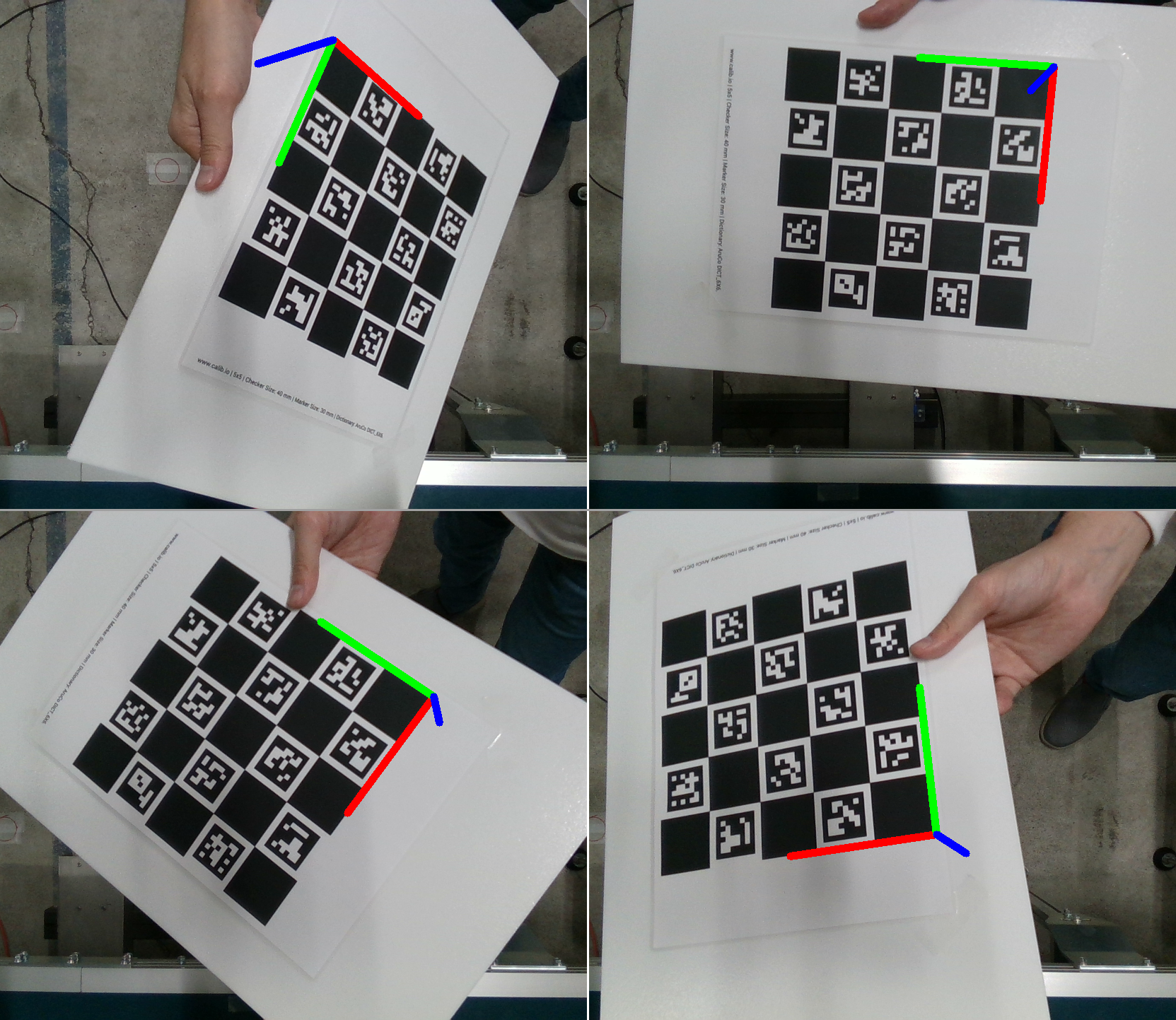
It can also be used for measuring internal parameters, external parameters, and lens distortion.
However, because of the presence of ArUco markers, the length of one side of the grid becomes somewhat large, resulting in fewer grid points compared to a regular CheckerBoard.
Therefore, it is necessary to collect a large amount of data for accurate measurement of internal parameters.
Even if part of the calibration pattern is hidden, the detected ArUco markers can interpolate the occlusion for pose estimation.
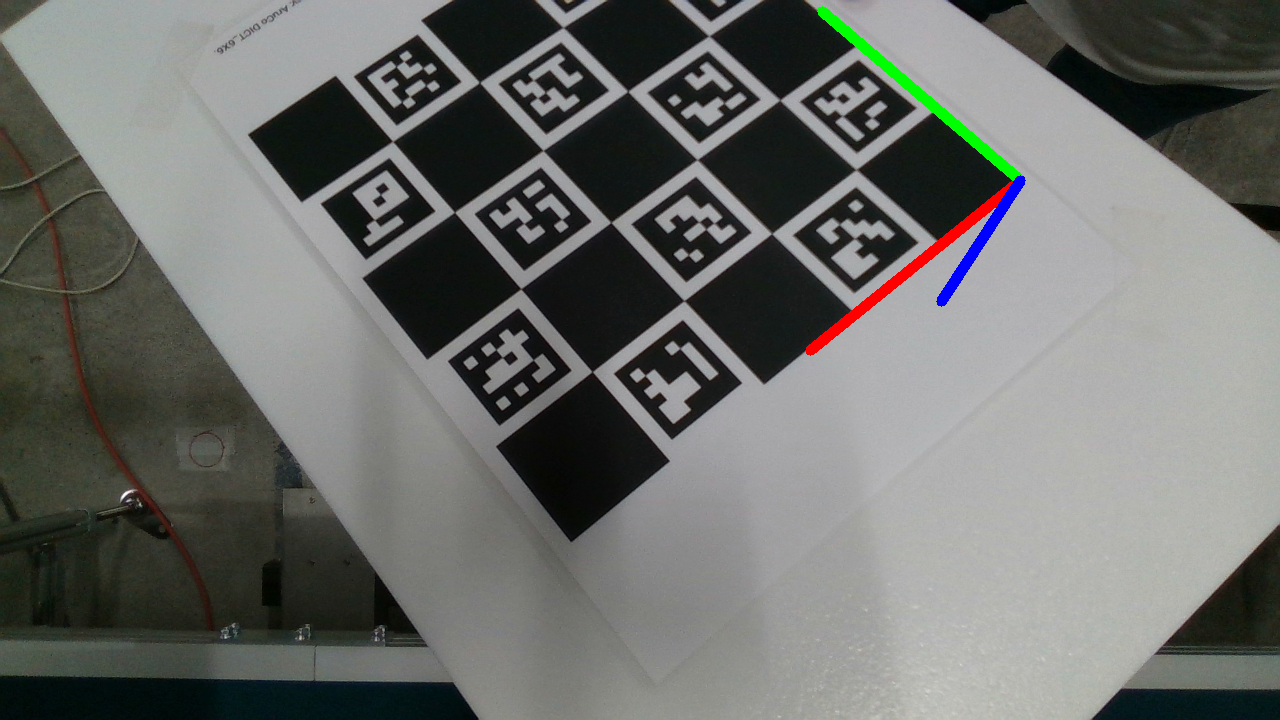
When measuring the external parameters of the camera and robot, a method of attaching the calibration pattern to the tip of the robot arm and photographing it with a camera is often used.
At that time, the robot arm itself may obstruct the camera's field of view and hide part of the calibration pattern, but ChArUco can still perform calibration without any problems in such cases.
Summary of Pattern Functions
#I have summarized the elements that can be measured for each pattern.
| Pattern | Internal Parameters & Lens Distortion | External Parameters |
|---|---|---|
| CheckerBoard | ◯ | × |
| CircleGrid | ◎ | × |
| Asymmetry-CircleGrid | ◎ | ◯ |
| ChArUco | ◯ | ◎ |
◎: Particularly suitable and recommended
◯: Calibration possible
×: Calibration not possible
Regarding accuracy, the following trends are observed:
CircleGrid = Asymmetry-CircleGrid > CheckerBoard ≧ ChArUco
Conclusion
#This time, I introduced calibration patterns available in OpenCV.
I hope this helps those who want to perform camera calibration in OpenCV but are unsure which pattern to use.
