Visualizing Dynamics That UML Cannot Fully Express Using Petri Nets
Back to TopTo reach a broader audience, this article has been translated from Japanese.
You can find the original version here.
# Is UML Alone Not Enough? If You Know Petri Nets, You Can Understand Systems More Deeply
#Purpose of This Article
#Originally, I planned to write an article on my findings from unraveling UML Format 2.5.1, but in the process I found that I needed to understand Petri net concepts, so I studied Petri nets. I decided to share what I learned, which is why I'm writing this article.
UML is a powerful modeling tool, but it can have limitations when it comes to expressing complex system behaviors and state transitions. In this article, I'll introduce the modeling technique called the "Petri net" to complement UML and gain a deeper understanding of systems.
By reading this article, you can expect to achieve the following:
- Reduce review comments based on how models are written and improve the quality of deliverables.
- When creating models during requirements analysis or similar tasks, correctly understand what your models actually mean.
- Understanding what models mean makes it easier to explain them to clients.
Since Petri net concepts frequently appear in the UML Format, this time I'll focus on Petri nets and explain the differences from UML as well as how to apply Petri nets.
What Is a Petri Net? Differences from UML
#A Petri net is a method invented by Carl Adam Petri in 1962 for mathematically describing discrete distributed systems. (Discrete distributed systems: Systems in which parallel, individually distributed actions—such as adjusting living room lighting or controlling air conditioning in a smart home system—are connected together to form one unified system.)
Both UML and Petri nets are tools for modeling system behavior, but they excel at different aspects.
- UML: Excellent for expressing the overall structure of a system and relationships between objects.
- Petri nets: Excellent for clearly representing state changes within a system, concurrent processing, and temporal flows.
For example, when modeling system behavior with a UML Activity diagram, you can understand what processes the system performs, but it's difficult to represent state changes between events (actions) and express temporal behavior along the time axis.
If a client asks for a more detailed explanation such as "what happens inside the system and in what order," using Petri nets might allow you to explain and represent it more accurately and clearly.
Basics of Petri Nets
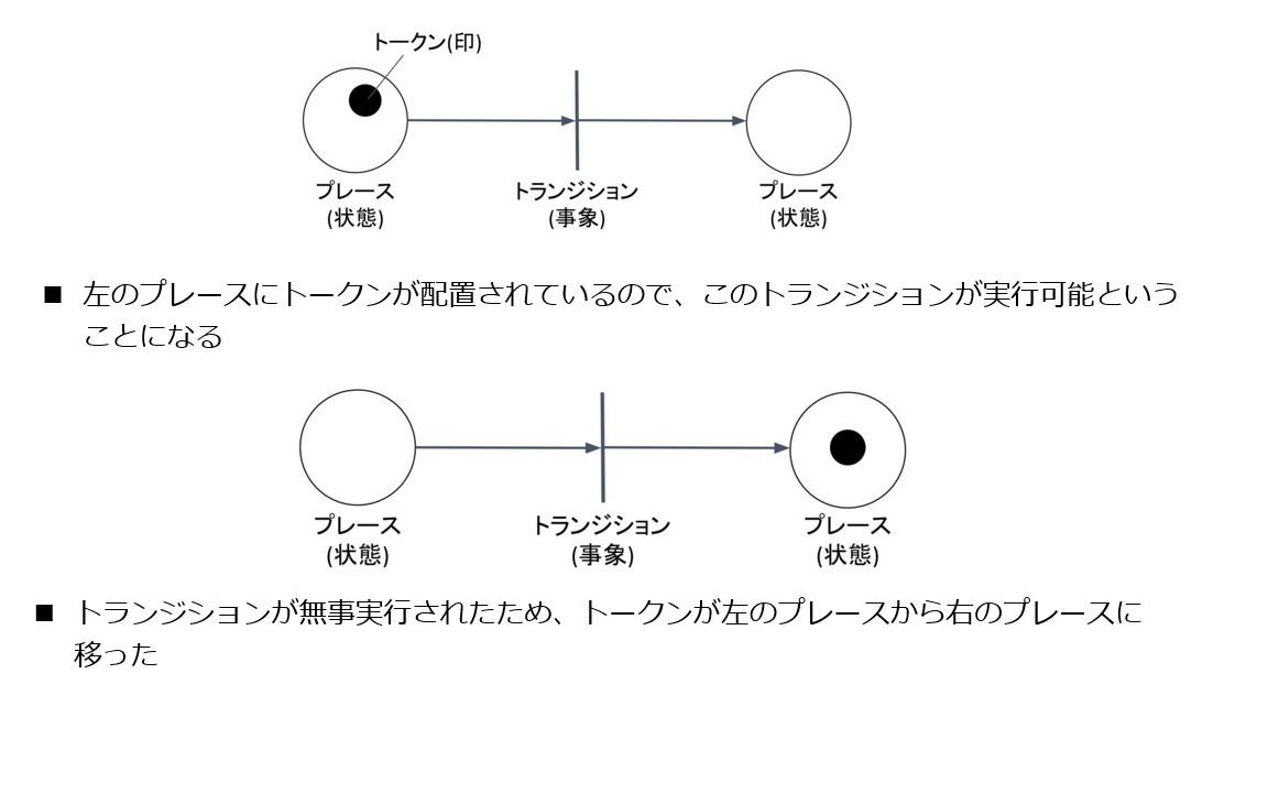
#The elements necessary for drawing a Petri net are as follows. A Petri net consists of places (states), transitions (state changes/events), the lines that connect them (input arcs, output arcs), and tokens.
- Place: A circular node representing a state
- Transition: A rectangular node representing a state change
- Input arc: A line connecting the previous state to the transition, representing the place(s) required for the transition to fire
- Output arc: A line connecting the transition to the next state, representing the place(s) used to transition to the subsequent state as a result of the transition firing
- Token: A black dot placed inside a place, indicating the local state of the system, i.e., which place currently holds the resource
This is the set of elements that make up a basic Petri net. Simple Petri nets are useful for modeling parallel processing—situations where multiple processes execute independently. Note that simple Petri nets can only model relatively straightforward problems. However, by using extended Petri nets (Colored Petri Nets, Timed Petri Nets, etc.), you can model complex systems.
An example model of such a simple Petri net is shown below.
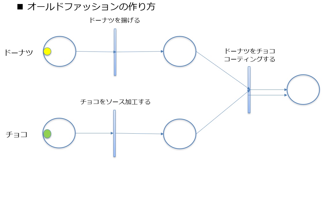
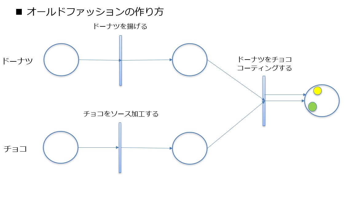
Based on this, let's represent the process of making an old-fashioned donut as an example using a Petri net. To make an old-fashioned donut, you need the donut itself and the chocolate for coating. As raw materials, we have an un-fried donut and chocolate that hasn't yet been processed into chocolate sauce as places. Of course, in this state, the tokens for both the donut and the chocolate are in the leftmost places.
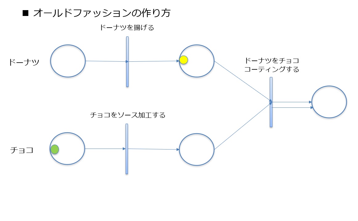
Here, when you fry the donut, the transition "Fry the Donut" fires and a token moves from the previous state to the next state.
Next, when you process the chocolate into a sauce for coating, the transition "Process Chocolate into Sauce" fires and the token moves from the previous state to the next state.
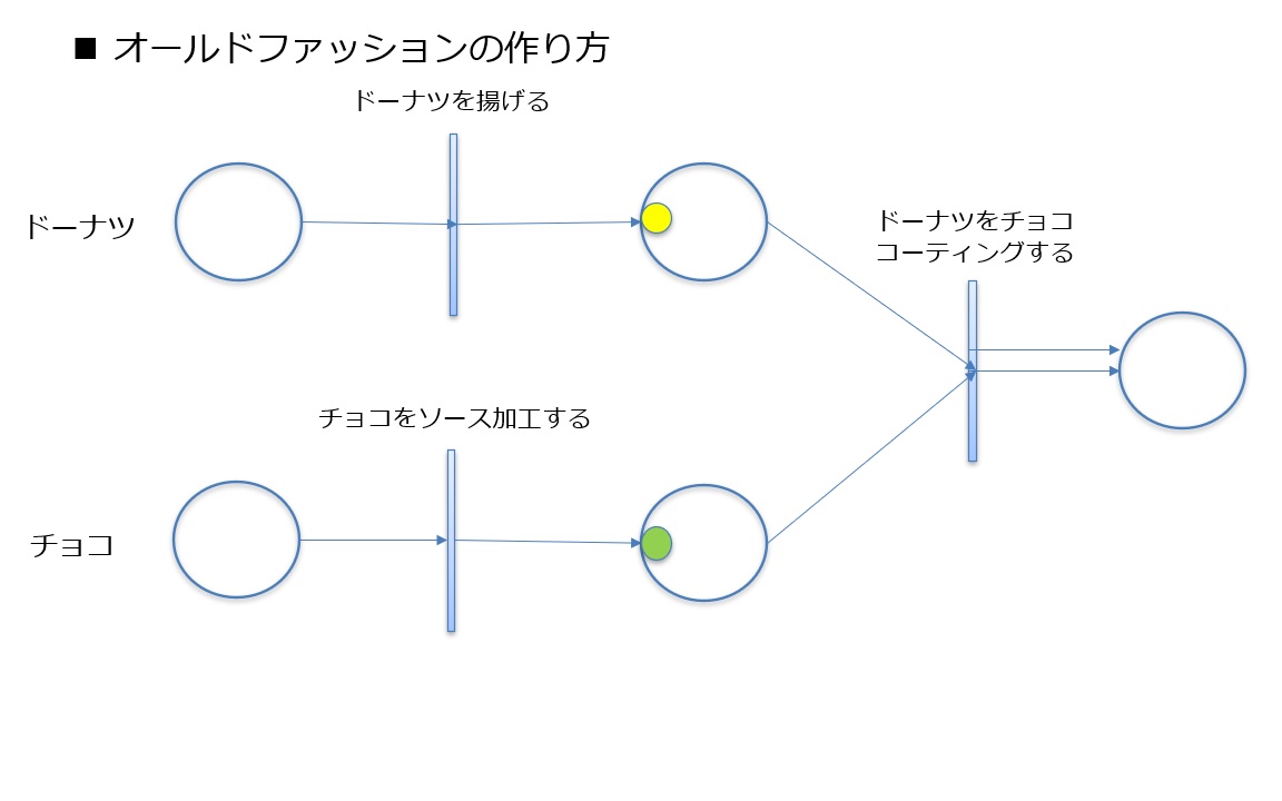
Finally, as a finishing step, when you coat the donut with chocolate sauce, the transition "Coat Donut with Chocolate" fires, and two tokens move from the two previous states to the next state.
Rules of Petri Nets
#Since there are specific constraints regarding tokens in Petri nets, this section explains those.
State Representation
#- A place represents the local state of the system based on the number of tokens it contains.
- One token corresponds to one resource. If there are k tokens in a given place, that indicates k resources exist in that place.
- If multiple tokens reside in the same place, they are indistinguishable.
In other words, tokens indicate how many resources are in a given place at a given time, without considering which specific token (resource) is present.
State Transition Rules
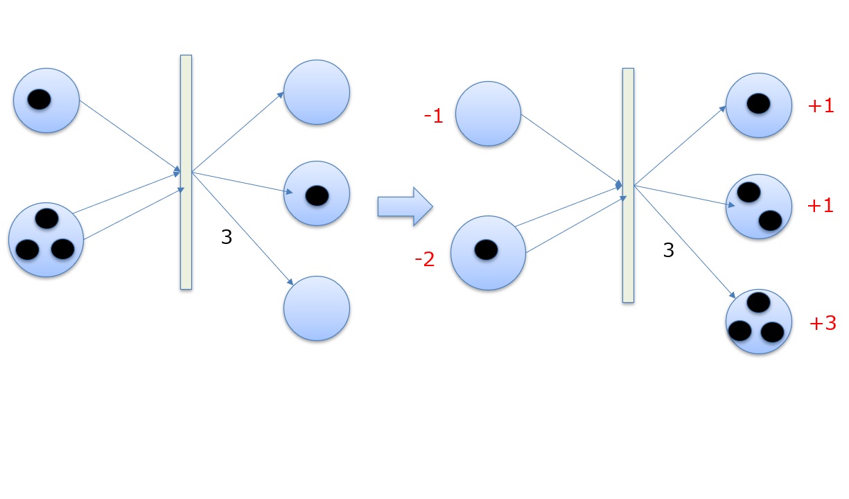
#- A transition is enabled when there are at least as many tokens in each input place as the weight of the corresponding arc. (Note: Arc weights are represented by assigning a number to the arrow; for example, a weight of 3 requires 3 tokens.)
- When a transition fires, the number of tokens equal to the weight of each input arc (number of arrows) is removed from the input places, and the number of tokens equal to the weight of each output arc (number of arrows) is added to the output places (subsequent states).
In other words, the total number of tokens in the entire Petri net remains constant, and no more tokens move than the number of arrows. Finally, the image below shows the movement of tokens before and after a transition fires.
Conclusion
#I became aware of Petri nets while interpreting the UML Format, and I found them to be a more primitive yet intuitively understandable representation technique compared to UML.
UML is helpful for understanding the structure of a system, but by combining it with Petri nets, you can gain a deeper understanding of the system's dynamic aspects.
- You're comfortable with UML but struggle to express system behavior...
- You want to explain the system's behavior concretely to clients...
If you're facing such concerns, why not consider leveraging Petri nets?
By understanding the strengths of both UML and Petri nets and using them appropriately, you should be able to design and develop systems more effectively.