Made a Ceiling Light Remote Control Powered by a Button Cell Using ATtiny13A [Development Edition]
Back to TopTo reach a broader audience, this article has been translated from Japanese.
You can find the original version here.
The previous article is here 【準備編】
Up until now, the preliminary preparations have finally been completed. From here on, we move on to the main circuit design and program development.
Goals for the Homemade Infrared Remote Control
#The goals were set as follows:
- Include as much functionality of the remote (HK9493) as possible
- Powered by a button cell (3V)
- Low power consumption
- Keep component costs low
Remote Control Operation Button Specifications
#As a result of analyzing the infrared transmission data in 【準備編】, the transmission data (commands) for the buttons turned out as follows.
| Command Array | ch1 | ch2 | ch3 | Long Press |
|---|---|---|---|---|
| Warm Color | 0x9139522C(0xA8) | 0x9539522C(0xAC) | 0x9939522C(0xA0) | 〇 |
| White Color | 0x9039522C(0xA9) | 0x9439522C(0xAD) | 0x9839522C(0xA1) | 〇 |
| Turn On | 0x2D09522C(0x24) | 0x3509522C(0x3C) | 0x3D09522C(0x34) | |
| Turn Off | 0x2F09522C(0x26) | 0x3709522C(0x3E) | 0x3F09522C(0x36) | |
| Brighter | 0x2A09522C(0x23) | 0x3209522C(0x3B) | 0x3A09522C(0x33) | 〇 |
| Darker | 0x2B09522C(0x22) | 0x3309522C(0x3A) | 0x3B09522C(0x32) | 〇 |
| Night Light | 0x2E09522C(0x27) | 0x3609522C(0x3F) | 0x3E09522C(0x37) | |
| All On | 0x2C09522C(0x25) | 0x3409522C(0x3D) | 0x3C09522C(0x35) | |
| Sleep 30 minutes | 0xA139522C(0x98) | 0xAA39522C(0x93) | 0xB339522C(0x8A) | |
| Channel Confirm | 0xDA39522C(0xE3) | 0xDB39522C(0xE2) | 0xDC39522C(0xE5) |
(0xNN) is the parity data, and “Long Press” indicates that the command supports long press so that brightness can be adjusted by holding down the button.
There are 3 channels, and by pressing the corresponding channel confirm button, only commands for that channel will be accepted.
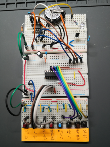
Circuit Diagram
#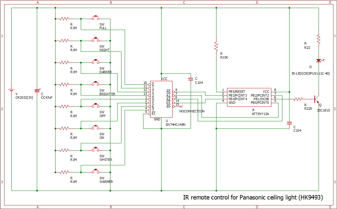
There are 8 switches for remote control on the left, connected to the ATtiny13A via a central module (encoder).
The infrared LED draws a high current—about 50mA to 100mA—but since the ATtiny13A cannot supply such a large current directly, a transistor is used.
Due to the large number of switches and the connection via the central module, there is extensive wiring.
Switch ON/OFF
#On the left side of the circuit diagram, there are 8 switches. These serve as the buttons for functions such as turning the remote on and off.
For beginners in circuit design (myself included), this may seem curious, so I’ve illustrated three similar circuits above. Can you tell the difference in the OUT voltage when the SW is turned ON/OFF?
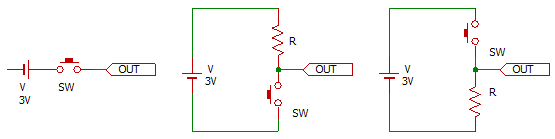
Left
When the SW is ON, the supply voltage of 3V is applied to OUT and current flows. When the SW is OFF, you might expect OUT to be 0V—but it isn’t!! It is not 0V because it is not connected anywhere and remains in an undefined state. Such a state is called “floating” or “high impedance” and must always be pulled to 0V or a defined voltage.
Center
When the SW is OFF, the supply voltage of 3V is applied to OUT. A current determined by the supply voltage divided by the resistor value (V/R) flows into OUT. When the SW is turned ON, OUT becomes 0V.
If resistor R were absent, the positive and negative terminals of the supply would be directly connected, resulting in a large current and a short circuit. However, by inserting resistor R, the current is limited; when R is large (from 10K to several MΩ), almost no current flows, preventing a short. In this case, the positive side of R is at 3V and the negative side at 0V, so OUT is 0V.
This resistor R is called a pull-up resistor, and the circuit is known as a pull-up configuration.
Right
This circuit is obtained by swapping the positions of resistor R and the SW from the center configuration.
When the SW is OFF, OUT is connected to the negative terminal, so it is 0V.
When the SW is ON, as before, the positive side of R is at 3V and the negative side at 0V; therefore, OUT becomes 3V.
In this case, R is called a pull-down resistor, and the circuit is known as a pull-down configuration.
In the circuit diagram, all the buttons are configured as pull-up circuits.
Pin Count Issue
#The ATtiny13A has 6 pins available as inputs (PB0 to PB5), but PB5 also serves as the reset and is used during programming. Since using it might cause problems during programming or remote control operation (unconfirmed), it was not used.
As a result, only 5 pins (other than 1 for RESET, 4 for GND, and 8 for VCC) are available. Furthermore, one of these is used as an output pin for lighting the LED during infrared transmission, leaving only 4 input pins in practice.
With only 4 pins and 8 switches, it is necessary to determine which switch is pressed [1]. What should be done? I considered the following methods.
A: Use ADC Conversion
Configure one pin as an analog input and, using different resistor values for each switch, measure the voltage to determine which switch is pressed.
B: Use an Encoder
Feed the 8 input lines into an encoder and receive the output on 3 or 4 lines. The resulting binary (3- or 4-bit number) will indicate which switch is pressed.
C: Use an IO Expander
Connect the 8 input lines to an IO expander, and let the IO expander communicate with the ATtiny13A via I2C (2 wires) to determine which switch is pressed.
When testing option A, I found that the ADC gives an 8‑bit result (0–255 for a maximum of 3V), but with 8 switches it would be necessary to create 8 distinct voltage ranges using different resistor values. Setting the threshold ranges was cumbersome and the accuracy poor, often leading to misdetections, so this option was ruled out.
Option B can be implemented using an encoder circuit—the SN74HC148N—and the number of pins required to connect to the ATtiny13A is just right.
Option C was judged impractical because writing the I2C communication program is troublesome, deviates from the main project, and would bloat the program size.
So, option B was adopted.
An IO expander is a circuit that expands (increases) the number of available input/output pins.
I2C (Inter Integrated Circuit) is a communication protocol that enables multiple modules to communicate using only 2 wires (a data line and a clock line). It is commonly used for communication with LCDs and simple sensors. It is pronounced “I-Squared-C” or “I2C.”
Looking at the datasheet (specifications) for the SN74HC148N [2], the correspondence between inputs and outputs is as shown in the table below.
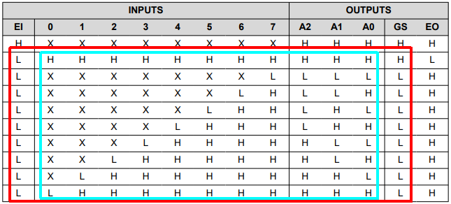
In the light blue box, by checking the H/L values of INPUTS 0 through 7 and OUTPUTS A0 through A2, you can determine which switch is pressed [3].
However, when only INPUT 0 is LOW (last row) and when all inputs 0–7 are HIGH (second row), OUTPUTS A0–A2 are identical (all HIGH). Thus, when the switch corresponding to INPUT 0 is pressed versus when nothing is pressed, the outputs are the same, making determination impossible.
To solve this, as shown in the red box, an additional input named EI (which is always LOW) was added—bringing the total number of input lines to 9—and GS was added to the outputs to yield 4 output lines.
This configuration produces one of 9 possible output patterns using 4 bits.
When OUTPUT EO is LOW, it indicates that no switch is pressed; this can be used for determination, but in any case, 4 output lines are required.
Note that input pins must be kept HIGH when not driven (i.e. they are low-active); therefore, pull-up resistors are used (see Switch ON/OFF).
You might say, "Then why not use a microcontroller with 8 available pins from the start?" but I wanted to create something using the ATtiny13A—consider it a demonstration of what can be accomplished 😅.
Bypass Capacitor
#The capacitor (C) might not be strictly necessary for operation, but it has the following benefits:
- It smooths out voltage changes (noise reduction)
- It supplies power during sudden increases in power consumption
A capacitor placed in parallel between the power supply (V) and ground (GND) bypasses noise; therefore, it is called a bypass capacitor (often abbreviated as “pass-con”).
The program is designed so that in the steady state it consumes almost no power (below 0.1µA), as will be described later; however, when a remote control button is pressed, the infrared LED lights up. Although infrared light is invisible, like a normal LED it emits light. Since it is used for remote control, it must emit a stronger light than a typical LED so that it can reach the infrared receiver on the main unit several meters away, drawing about 50 to 100mA [4]. This causes a sudden increase in power consumption and a voltage drop.
In battery-powered applications, the battery is fine when new, but as power is consumed, the voltage gradually drops. When the voltage nears the microcontroller’s minimum operating voltage, instability can result; however, including a bypass capacitor helps the circuit “ride through” voltage drops, allowing the battery to be used longer (and more efficiently).
Program
#The entire program is about 280 lines long.
- Approximately 90 lines cover header includes, #define definitions, and data array declarations
- About 90 lines in setup()
- Roughly 70 lines in loop()
The control logic (setup(), loop(), and other functions) exceeds 100 lines. However, because each section is well commented and structured with curly-brace blocks—and bit-level operations for register settings are broken out by line—the overall content remains quite simple despite the large number of lines.
#include <avr/io.h>
#include <util/delay.h>
#include <util/delay_basic.h>
#include <avr/interrupt.h>
#include <avr/sleep.h>
#include <wiring_private.h>
#include <avr/pgmspace.h>
#include <avr/eeprom.h>

#define IR_COMMAND_WARMER   0 // Warm Color
#define IR_COMMAND_WHITER   1 // White Color
#define IR_COMMAND_ON       2 // Turn On
#define IR_COMMAND_OFF      3 // Turn Off
#define IR_COMMAND_BRIGHTER 4 // Brighter
#define IR_COMMAND_DARKER   5 // Darker
#define IR_COMMAND_NIGHT    6 // Night Light
#define IR_COMMAND_FULL     7 // All On
#define IR_COMMAND_NONE    15 // None

#define HEADERMARK       1035 // 8T (3450us)
#define HEADERSPACE       510 // 4T (1700us)
#define DATAMARK          135 // 1T (450us)
#define ONESPACE          390 // 3T (1300us)
#define ZEROSPACE         135 // 1T (450us)

#define COMMAND_SIZE  5

// Lighting Control
const byte command_1ch_0[] PROGMEM = {0x91, 0x39, 0x52, 0x2C, 1};
const byte command_1ch_1[] PROGMEM = {0x90, 0x39, 0x52, 0x2C, 1};
const byte command_1ch_2[] PROGMEM = {0x2D, 0x09, 0x52, 0x2C, 0};
const byte command_1ch_3[] PROGMEM = {0x2F, 0x09, 0x52, 0x2C, 0};
const byte command_1ch_4[] PROGMEM = {0x2A, 0x09, 0x52, 0x2C, 1};
const byte command_1ch_5[] PROGMEM = {0x2B, 0x09, 0x52, 0x2C, 1};
const byte command_1ch_6[] PROGMEM = {0x2E, 0x09, 0x52, 0x2C, 0};
const byte command_1ch_7[] PROGMEM = {0x2C, 0x09, 0x52, 0x2C, 0};
const byte command_2ch_0[] PROGMEM = {0x95, 0x39, 0x52, 0x2C, 1};
const byte command_2ch_1[] PROGMEM = {0x94, 0x39, 0x52, 0x2C, 1};
const byte command_2ch_2[] PROGMEM = {0x35, 0x09, 0x52, 0x2C, 0};
const byte command_2ch_3[] PROGMEM = {0x37, 0x09, 0x52, 0x2C, 0};
const byte command_2ch_4[] PROGMEM = {0x32, 0x09, 0x52, 0x2C, 1};
const byte command_2ch_5[] PROGMEM = {0x33, 0x09, 0x52, 0x2C, 1};
const byte command_2ch_6[] PROGMEM = {0x36, 0x09, 0x52, 0x2C, 0};
const byte command_2ch_7[] PROGMEM = {0x34, 0x09, 0x52, 0x2C, 0};
const byte command_3ch_0[] PROGMEM = {0x99, 0x39, 0x52, 0x2C, 1};
const byte command_3ch_1[] PROGMEM = {0x98, 0x39, 0x52, 0x2C, 1};
const byte command_3ch_2[] PROGMEM = {0x3D, 0x09, 0x52, 0x2C, 0};
const byte command_3ch_3[] PROGMEM = {0x3F, 0x09, 0x52, 0x2C, 0};
const byte command_3ch_4[] PROGMEM = {0x3A, 0x09, 0x52, 0x2C, 1};
const byte command_3ch_5[] PROGMEM = {0x3B, 0x09, 0x52, 0x2C, 1};
const byte command_3ch_6[] PROGMEM = {0x3E, 0x09, 0x52, 0x2C, 0};
const byte command_3ch_7[] PROGMEM = {0x3C, 0x09, 0x52, 0x2C, 0};

// Channel Confirm
const byte command_channel_1[] PROGMEM = {0xDA, 0x39, 0x52, 0x2C, 0};
const byte command_channel_2[] PROGMEM = {0xDB, 0x39, 0x52, 0x2C, 0};
const byte command_channel_3[] PROGMEM = {0xDC, 0x39, 0x52, 0x2C, 0};

// Sleep 30 minutes
const byte command_sleep30_1[] PROGMEM = {0xA1, 0x39, 0x52, 0x2C, 0};
const byte command_sleep30_2[] PROGMEM = {0xAA, 0x39, 0x52, 0x2C, 0};
const byte command_sleep30_3[] PROGMEM = {0xB3, 0x39, 0x52, 0x2C, 0};

// List of Infrared Transmission Data
const byte * const commands[] PROGMEM = {
    command_1ch_0,
    command_1ch_1,
    command_1ch_2,
    command_1ch_3,
    command_1ch_4,
    command_1ch_5,
    command_1ch_6,
    command_1ch_7,
    command_2ch_0,
    command_2ch_1,
    command_2ch_2,
    command_2ch_3,
    command_2ch_4,
    command_2ch_5,
    command_2ch_6,
    command_2ch_7,
    command_3ch_0,
    command_3ch_1,
    command_3ch_2,
    command_3ch_3,
    command_3ch_4,
    command_3ch_5,
    command_3ch_6,
    command_3ch_7,
    command_channel_1,
    command_channel_2,
    command_channel_3,
    command_sleep30_1,
    command_sleep30_2,
    command_sleep30_3,
};

// Offset for Channel Switching
byte command_offset = 0;

void setup() {
    // Port Setup
    {
        sbi(DDRB, DDB1);

        sbi(PORTB, PORTB0);
        sbi(PORTB, PORTB2);
        sbi(PORTB, PORTB3);
        sbi(PORTB, PORTB4);
    }

    // Timer Setup
    {
        TCCR0A =
            (0 << COM0A1)
          | (0 << COM0A0)
          | (0 << COM0B1)
          | (0 << COM0B0)
          | (1 << WGM01)
          | (1 << WGM00)
          ;

        TCCR0B =
            (0 << FOC0A)
          | (0 << FOC0B)
          | (1 << WGM02)
          | (0 << CS02)
          | (0 << CS01)
          | (1 << CS00)
          ;

        OCR0A = 31;
        OCR0B = 11;
        TIMSK0 = 0;
    }

    // Power Saving Setup
    {
        sbi(PRR, PRADC);
    }

    // Channel configuration Read/Write and channel configuration transmission
    {
        uint8_t eeprom_address = 0x00;
        uint8_t read_data = eeprom_read_byte(&eeprom_address);

        if (read_data == 0 || read_data == 8 || read_data == 16) {
            command_offset = read_data;
        } else {
            command_offset = 0;
            eeprom_update_byte(&eeprom_address, command_offset);
        }

        _delay_ms(20);

        byte command_no = get_command_no();

        if (command_no == IR_COMMAND_ON) {
            read_data = 0;
            command_no = 0;
        } else if (command_no == IR_COMMAND_FULL) {
            read_data = 8;
            command_no = 1;
        } else if (command_no == IR_COMMAND_NIGHT) {
            read_data = 16;
            command_no = 2;
        } else {
            read_data = command_offset;
        }

        if (read_data != command_offset) {
            command_offset = read_data;
            eeprom_update_byte(&eeprom_address, command_offset);

            byte buffer[COMMAND_SIZE] = {0};
            command_offset = 24;
            get_command_data(command_no, buffer);
            ir_send(buffer);
            command_offset = read_data;
        }
    }

    // Interrupt Setup and Sleep Configuration
    cli();
    {
        sbi(GIMSK, PCIE);

        sbi(PCMSK, PCINT0);
        sbi(PCMSK, PCINT2);
        sbi(PCMSK, PCINT3);
        sbi(PCMSK, PCINT4);

        set_sleep_mode(SLEEP_MODE_PWR_DOWN);
    }
    sei();
}

void loop() {
    sleep_mode();

    _delay_ms(20);

    byte command_no;
    byte buffer[COMMAND_SIZE] = {0};
    byte *longPress = &buffer[4];

    do {
        if (*longPress) {
            _delay_ms(100);
        }

        command_no = get_command_no();

        if (command_no == IR_COMMAND_NONE) {
            return;
        }

        get_command_data(command_no, buffer);
        ir_send(buffer);
    } while (*longPress);
}

// Get Command Number
byte get_command_no() {
    return
          ((bit_is_set(PINB, PINB4) ? 1 : 0) << 3)
        | ((bit_is_set(PINB, PINB2) ? 1 : 0) << 2)
        | ((bit_is_set(PINB, PINB0) ? 1 : 0) << 1)
        | ((bit_is_set(PINB, PINB3) ? 1 : 0) << 0)
        ;
}

// Retrieve infrared transmission data for the specified command number
void get_command_data(byte command_no, byte *out) {
    memcpy_P(out, (byte *)pgm_read_byte(
                &commands[command_offset + command_no]), COMMAND_SIZE);
}

// Infrared Transmission
void ir_send(byte *command) {
    // Generate data segment
    uint32_t data =
          ((uint32_t)command[0] << 24)
        | ((uint32_t)command[1] << 16)
        | ((uint32_t)command[2] <<  8)
        | ((uint32_t)command[3] <<  0)
        ;

    // Calculate parity
    byte parity = command[0] ^ command[1];

    // Transmit header
    sbi(TCCR0A, COM0B1);
    _delay_loop_2(HEADERMARK);
    cbi(TCCR0A, COM0B1);
    _delay_loop_2(HEADERSPACE);

    // Transmit data segment
    for (uint8_t i = 0; i < 32; i++) {
        sbi(TCCR0A, COM0B1);
        _delay_loop_2(DATAMARK);
        cbi(TCCR0A, COM0B1);
        _delay_loop_2((data>>i) & 1 ? ONESPACE : ZEROSPACE);
    }

    // Transmit parity
    for (uint8_t i = 0; i < 8; i++) {
        sbi(TCCR0A, COM0B1);
        _delay_loop_2(DATAMARK);
        cbi(TCCR0A, COM0B1);
        _delay_loop_2((parity>>i) & 1 ? ONESPACE : ZEROSPACE);
    }

    // Transmit trailer
    sbi(TCCR0A, COM0B1);
    _delay_loop_2(DATAMARK);
    cbi(TCCR0A, COM0B1);
    _delay_loop_2(ZEROSPACE);
}
Compilation (Fuse) Settings
#To achieve low power consumption, the following changes were made:
- Disabled BOD (Brown Out Detection)
- Changed the clock frequency to 1.2MHz
Disable BOD
Although the supply voltage is 3V, if it drops below the microcontroller’s operating voltage (1.8V for the ATtiny13A), malfunctions may occur. BOD detects a voltage drop and resets the microcontroller to halt operation.
It is likely that before the microcontroller malfunctions, a low voltage would prevent infrared transmission (the forward voltage required to light the LED would be insufficient). Moreover, disabling BOD significantly reduced power consumption and contributed greatly to overall power saving.
Clock Frequency Change
Basically, AVR microcontrollers can operate at lower voltages when the clock frequency is reduced.
While the default clock frequency is 9.6MHz, for infrared transmission it is only necessary to generate a 38KHz modulation and a delay of about 450µs; a high frequency is not needed.
Since the timer depends on the clock frequency (for generating the 38KHz modulation and calculating delay times), and to avoid lengthy calculations, the frequency was set to 1.2MHz—a value commonly used online.
Data Declarations
#After including header files and defining constants, each command is declared as an array.
There are 30 commands for lighting control, each consisting of 4 bytes (excluding parity), amounting to 120 bytes of data. Since, as mentioned earlier, the SRAM is only 64 bytes, clever optimization was necessary.
const byte command_1ch_0[] PROGMEM = {0x91, 0x39, 0x52, 0x2C, 1};
The last element of each array is set to 1 for commands that support long press and 0 for those that do not, so that long press capability can be determined.
PROGMEM is a special keyword in Arduino sketches that stores data in flash memory (program space) instead of SRAM. This allowed for defining more data than the available SRAM. Although the program size increased, it still remained within the flash memory capacity.
Compilation log
Of the maximum 1024 bytes of flash memory, the sketch is using 972 bytes (94%).
Of the maximum 64 bytes of RAM, global variables are using 1 byte (1%), leaving 63 bytes available for local variables.
setup() Processing
#Here, the registers are configured. Since you need to know from the datasheet which registers are set to what in order to fully understand the program, a mere glance at the code might not be sufficient. For details, please refer to the datasheet; the following is only a brief explanation.
The function sbi(register, bit) sets the specified bit in the given register to 1, and cbi(register, bit) clears the specified bit (sets it to 0).
Port Setup
- PB1 (pin6) is connected to the infrared LED, so it is configured as an output port.
- The 8 buttons connected to the encoder output HIGH when OFF (they are low-active), so PB0, PB2, PB3, and PB4 are preset to HIGH.
Timer Setup
This is configured to generate a 38KHz modulated signal (a signal that toggles ON/OFF at 38KHz).
- Set the waveform generation mode to Fast PWM
- OCR0A = 31 is calculated from ((1.2MHz / 38kHz) / 1 (prescaler)) - 1 = 30.6
- OCR0B = 11 is calculated to set the duty cycle to 1/3, i.e. (1.2MHz / 38kHz) / 3 = 10.5
The 38KHz waveform is generated using the microcontroller’s timer; therefore, in the program (within the loop function), it only needs to specify whether to output from PB1 (pin6) or not, resulting in very simple control.
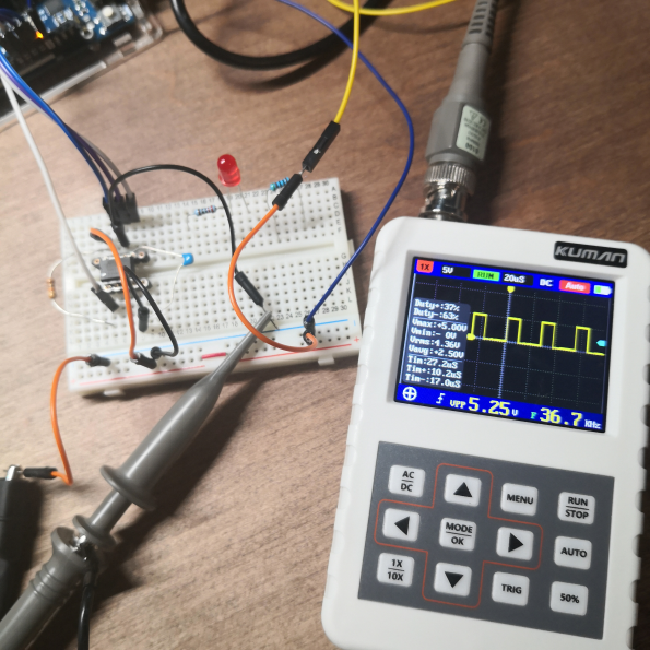
The image below shows the waveform measured with a simple oscilloscope. The square wave is output at approximately 36.7kHz. Although it isn’t exactly 38KHz, an error of this magnitude is acceptable for infrared transmission.
Power Saving Setup
The settings reduce power consumption of the A/D converter, although they only take effect during active mode or when using set_sleep_mode(SLEEP_MODE_IDLE), so they might not be necessary. In this program, the sleep mode is set to SLEEP_MODE_PWR_DOWN.
Read/Write for Infrared Transmission Channel Configuration
The remote control has a channel switching switch (with three settings) and a confirm button. Since the channel setting is used only infrequently after it is set, I originally planned not to implement it. However, since there was available space in the program, I implemented it. Note that all of the ATtiny13A’s ports are already in use, so there are no spare pins. After much deliberation on how to implement switching, I decided to set the channel based on the type of button pressed when power is applied (when the button cell is attached and the setup function is called).
| Button | Channel Setting |
|---|---|
| Not pressed | Saved channel |
| Turn On Button | 1ch |
| Night Light Button | 2ch |
| All On Button | 3ch |
Channel settings are written to EEPROM, so the configured channel is retained even if the button cell is replaced.
Interrupt and Sleep Setup
- The interrupt type is set to trigger when a pin’s state changes.
- Pin change interrupts are enabled on the encoder outputs (PB0, PB2, PB3, PB4).
- The sleep mode is set to SLEEP_MODE_PWR_DOWN.
There are three sleep modes—SLEEP_MODE_IDLE, SLEEP_MODE_ADC, and SLEEP_MODE_PWR_DOWN—which operate as shown in the table below.
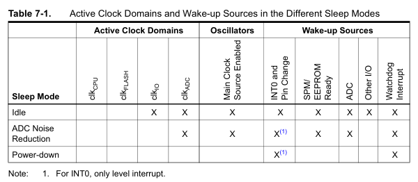
Setting the sleep mode to SLEEP_MODE_PWR_DOWN stops all clocks and disables the transmitting circuitry, putting the microcontroller into a deep sleep mode. All activity stops except for monitoring interrupts, so power consumption drops to below 0.1µA, nearly eliminating power draw.
The only ways to wake from sleep are:
- An external interrupt via INT0 or a pin change interrupt
- A watchdog timer interrupt
Since pin change interrupts are enabled on the encoder outputs (PB0, PB2, PB3, PB4), a change in pin state (i.e. a button press) wakes the microcontroller.
loop() Processing
#Main Loop Processing
This is the program’s main routine.
- The program enters sleep mode using sleep_mode() and waits here until a button is pressed.
- When a button is pressed and a pin change interrupt wakes the microcontroller, it waits 20ms to debounce.
- It identifies the pressed button, retrieves the corresponding command data, and transmits the infrared signal (by toggling the infrared LED).
- If the pressed button supports long press, it waits 100ms and repeats the process.
- Once loop() completes, it is called again immediately, returning to step 1.
Debouncing is the phenomenon where a button or switch causes mechanical vibrations when toggled, resulting in rapid on/off transitions. This can trigger multiple interrupts from a single button press.
Get Command Number
The outputs from the encoder (PB0, PB2, PB3, PB4) are bit-shifted to form a 4‑bit number, which is used as the command number.
Retrieve the Infrared Transmission Data for a Specified Command Number
As explained in Data Declarations, the command data is stored in flash memory, so here the command data stored in flash is retrieved.
Infrared Transmission
- Generate the transmission data from the command data array by bit-shifting to create a 32‑bit value.
- Calculate parity. The parity is computed as the exclusive OR (xor) of the data codes:
data[0] ^ data[1]. - Transmit the header: output ON for 8T, then OFF for 4T.
- Transmit the data segment: for each bit (obtained by right-shifting the command data), choose the clear wait time based on the least significant bit’s value.
- Transmit the parity, doing the same as in the header transmission for the parity data.
- Transmit the trailer: although an OFF period of at least 8ms is normally required, the following seems to work fine.
According to measurements with the IRremote library, T is 450µs. To measure this interval, the function _delay_loop_2(loop_count) defined in ATTiny13A’s util/delay_basic.h is used.
According to the datasheet, _delay_loop_2(1) consumes 4 CPU cycles. With a CPU frequency (F_CPU) of 1.2MHz, that is 1,200,000[Hz]/4[cycles] = 300,000, meaning 300,000 loop counts correspond to 1 second.
With the argument being a 16‑bit counter (up to 65,536), using _delay_loop_2(30000) produces a 100ms delay.
From this, to wait for 1T (450µs), _delay_loop_2(135) is used. The loop_count values for 8T, 4T, and 3T are as follows:
#define headerMark  1035 // 8T (3450us): 3450*30000/100000 = 345*3 = 1035
#define headerSpace  510 // 4T (1700us): 1700*30000/100000 = 170*3 =  510
#define dataMark     135 // 1T (450us) : 450*30000/100000 =  45*3 =  135
#define oneSpace     390 // 3T (1300us): 1300*30000/100000 = 130*3 =  390
#define zeroSpace    135 // 1T (450us) : 450*30000/100000 =  45*3 =  135
Conclusion
#After some trial and error, I believe I was able to fully utilize the microcontroller’s capabilities to achieve low power consumption and low cost, while keeping the loop() function simple. There is one minor regret in that the “Sleep 30 minutes” command hasn’t been implemented, but I hope to tackle that in another opportunity.
Next up is 【基板・ケース作成編】.
Simultaneous pressing of multiple switches was not taken into account. ↩︎
SN74HC148N Datasheet. It is very inexpensive, priced at 30 yen at Akizuki Denshi. ↩︎
X is a value that does not affect the determination. ↩︎
In reality, the infrared LED is pulsed at 38KHz (it rapidly toggles ON and OFF) rather than being continuously lit. ↩︎