使用免费OSS工具SysON开始SysMLv2建模(6)~创建ActionFlow
Back to Top为了覆盖更广泛的受众,这篇文章已从日语翻译而来。
您可以在这里找到原始版本。
在上一篇文章中,我们创建了 Action Definition 和 Action Usage。
在本文中,我们将使用它们来创建 ActionFlow。
SysMLv2 标准中提供了用于显示 Action 之间连接的 ActionFlowView。
要创建 ActionFlow,使用此 ActionFlowView 最为合适。
然而,在 SysON 的文档中,Action Flow View 页面标注为“开发中(under development)”。
本系列使用的 v2025.8.0 版本,以及撰写时的最新 main 分支也都如此。
因此本次,我们将在元素的 Graphical Compartment 中创建 ActionFlow。
Graphical Compartment 是指在 Part 或 Action 的边框内显示图形化视图的区块。
在本文中,主要介绍创建流程。
有关元素添加方法等操作,请参阅本系列之前的文章。
创建 Action Flow(其一)
#"Introduction to the SysML v2 Language Textual Notation" 幻灯片30的图,让我们试着绘制一下。
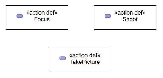
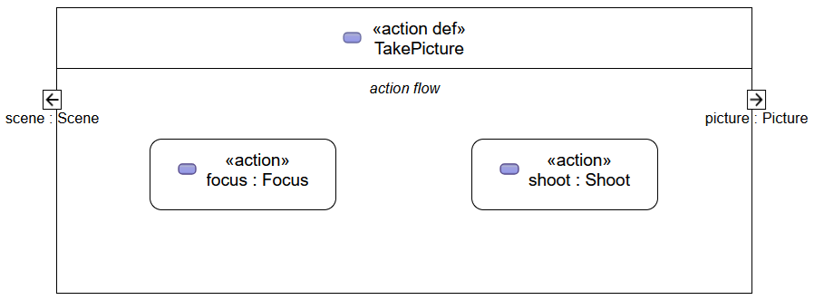
打开 General View,创建三个 Action Definition。
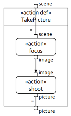
将创建的 Action Definition 名称依次修改为 "Focus"、"Shoot"、"TakePicture"。
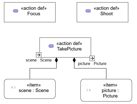
在 "TakePicture" 中分别添加一个输入 Item 和一个输出 Item。
将输入 Item 名称修改为 "scene : Scene",输出 Item 名称修改为 "picture : Picture"。
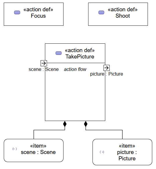
在 "TakePicture" 上打开 Manage Visibility 上下文菜单,勾选 "action flow"。
这样就会在 "TakePicture" 中显示用于展示 Action Flow View 的 Graphical Compartment。
在 "TakePicture" 的 action flow 区块上右击,从上下文菜单创建两个 Action Usage。
将创建的 Action Usage 名称依次修改为 "focus : Focus" 和 "shoot : Shoot"。
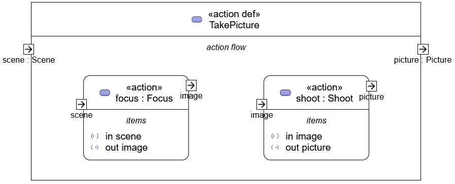
在 Action Usage "focus" 中分别添加一个输入 Item 和一个输出 Item。
将输入 Item 名称修改为 "scene",输出 Item 名称修改为 "image"。
同样地,在 Action Usage "shoot" 中分别添加一个输入 Item 和一个输出 Item。
将输入 Item 和输出 Item 名称分别修改为 "image" 和 "picture"。
选择 "TakePicture" 的输入 Item "scene"。
拖动其外侧显示的 ">" 并在 "focus" 的输入 Item 上释放,就会显示选择连接类型的菜单。
在菜单中选择 "New Binding Connector As Usage (bind)"。
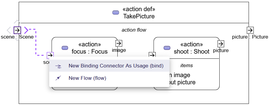
两个 Item 之间会添加一条连接线(Connector)。
同时,在该连接线附近会显示一个 "="。
这就是 Binding Connection。
同样,将 Action Usage "shoot" 的输出 Item 与 "TakePicture" 的输出 Item "picture" 用 Connector 连接。
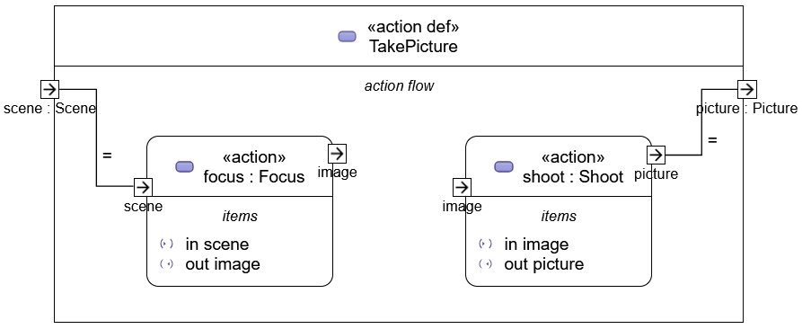
将 "focus" 的输出 Item 与 "shoot" 的输入 Item 连接。
同样通过拖放弹出连接类型菜单,这次在菜单中选择 "New Flow (flow)"。
将会添加一条带箭头的线。
这就是 Flow Connection。
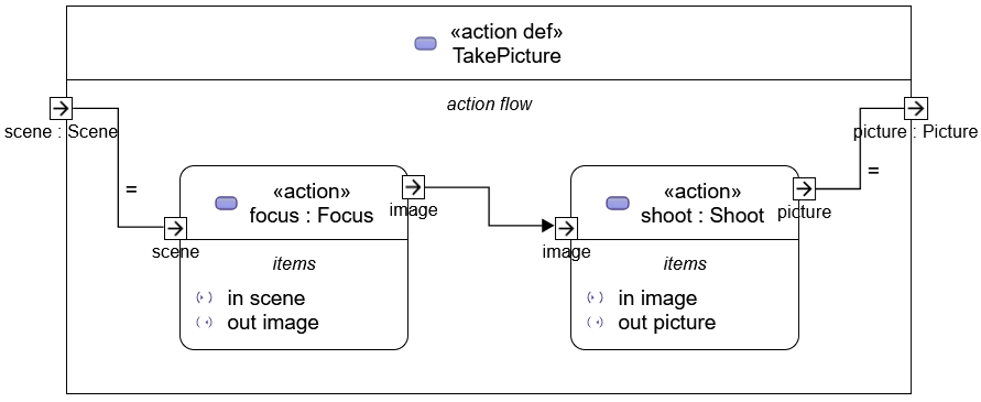
隐藏不需要的元素后,即可完成绘制。
创建 Action Flow(其二)
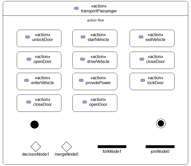
#这次,我们再试着绘制一个例子。
"Intro to the SysML v2 Language-Graphical Notation.pdf" 幻灯片58的图。
使用了分支和合并等几个 Control Node。
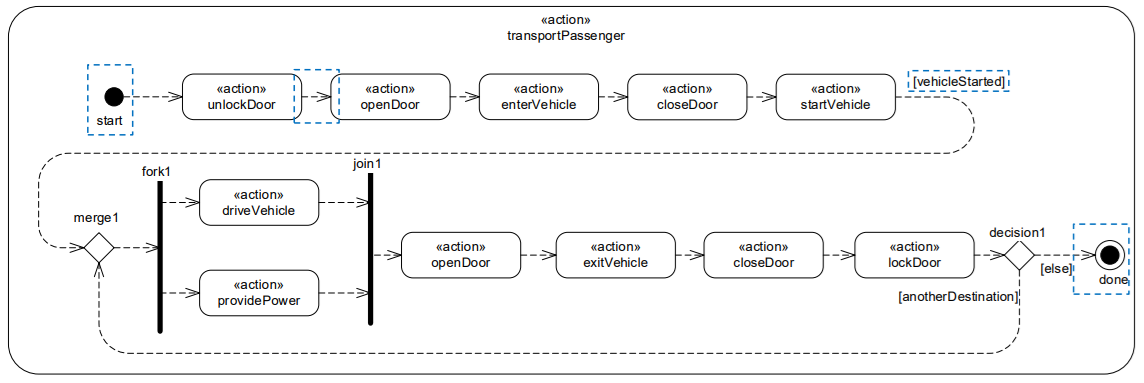
打开 General View,添加一个 Action Usage。
将添加的 Action Usage 名称修改为 "transportPassenger"。
在 "transportPassenger" 的 Manage Visibility 中勾选 "action flow"。
在显示的 action flow 区块中添加 Action Usage。
根据示例添加 11 个 Action Usage,并依次修改名称。
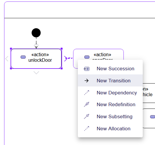
在 action flow 区块上右击,从弹出的上下文菜单的 "Behavior" 中添加所需的 Control Node。
似乎无法更改 Decision Node 或 Merge Node 的大小,也无法将 Fork Node 和 Join Node 纵向拉长。
选择 Control Node 或 Action Usage 时,拖动外侧显示的 ">" 并释放,以 Control Node 或 Action Usage 为起点连接流程。
连接时从上下文菜单中选择 "New Transition"。
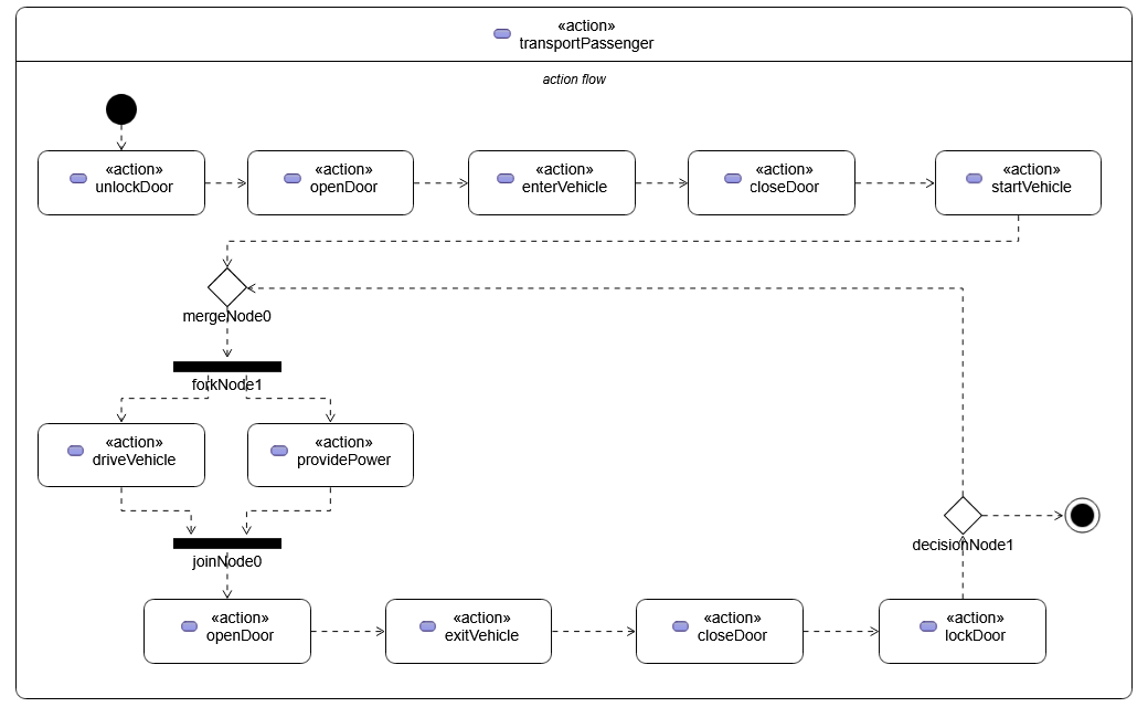
重新布局 action flow 的元素,已完成流程绘制。
接下来本来只剩添加 Guard 条件就可完成绘制,但没找到该步骤。
使用文本记法创建 Action Flow
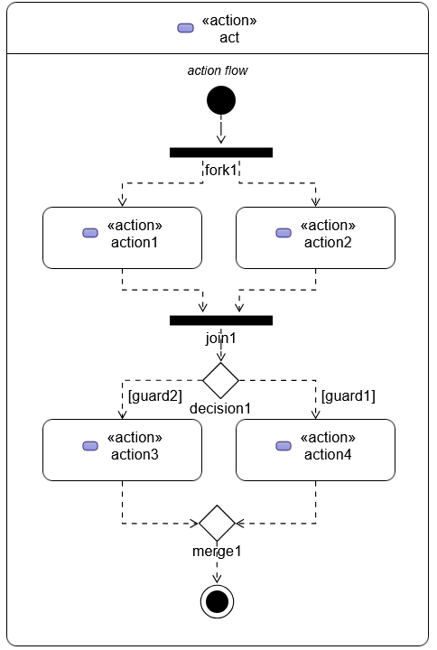
#使用文本记法,可以添加 Guard 条件。
参考 SysMLv2 规格书第 92 页表中记载的文本记法,编写如下内容。
由于 Guard 必须是 Boolean,因此将其作为 attribute 添加。
terminate 不会显示,因此改为 done。
action act {
	attribute guard1 : ScalarValues::Boolean;
	attribute guard2 : ScalarValues::Boolean;

	first start;
	then fork fork1;
		then action1;
		then action2;
	action action1;
		then join1;
	action action2;
		then join1;
	join join1;
	then decide decision1;
		if guard2 then action3;
		if guard1 then action4;
	action action3;
		then merge1;
	action action4;
		then merge1;
	merge merge1;
	then done;
}
让 SysON 读取该文本生成对象,并在 General View 中显示和格式化,效果如图所示。
总结与下回预告
#SysMLv2 规格书中还包含其他 Action Flow 示例。
同时,本系列所使用的文档中,也记录了除上述之外的 Action Flow。
但在本系列使用的 SysON 中,无法用图形化记法呈现所有这些 Action Flow。
另一方面,从 GitHub 的提交日志可以看出,SysON 的开发每天都在进行。
期待未来版本,包括 Action Flow View 的改进。
下次,我们将创建 State Definition 和 State Usage。
State 也仍在开发中,让我们看看能做到什么程度吧。