Let's Play with Cutting-Edge Robots × AI! A Guide to Experiencing Multimodal AI and Setting Up the Environment with LeRobot and SO-101
Back to TopTo reach a broader audience, this article has been translated from Japanese.
You can find the original version here.
Who This Is For
#- People who are interested in AI in the robotics field—such as multimodal AI, physical AI, imitation learning, and reinforcement learning—but don't know where to start
- People who feel they can't try out real robots because the price of the actual machines is too high
- People who want to learn by hands-on practice but wish to start at low cost
Introduction
#In this article, we will use the open-source project LeRobot and the open-source arm robot SO-101 as examples to explain the technology behind multimodal AI and the steps to set up the environment.
The ultimate goal is to replicate an action where, when you move one arm, the other arm follows the same movement (see the GIF below).
Terminology
#What Is Multimodal AI
#In traditional robotics development, multiple technologies (modalities) such as the robot body, cameras, and communication protocols operated independently, and the output data formats differed, making it difficult to integrate them into a single system.
In recent years, advances in Transformer-based models and other techniques have driven research and implementation of "multimodal AI," which integrates multiple modalities such as images, audio, text, and sensor readings, making it easier to handle and combine different data formats than before.
Consequently, in the robotics field, there is growing expectation that these issues will be resolved, and development leveraging multimodal AI is on the rise.
There is a similar term called "Physical AI." This term focuses on learning and decision-making in robots and the physical world, and it overlaps with multimodal AI in many aspects; however, in this article, we will not distinguish between them and will refer to everything as "multimodal AI."
What Is LeRobot
#Official repository: LeRobot
![]()
LeRobot is an open-source robotics library released by Hugging Face that provides models, datasets, and tools for real robots. By using LeRobot, you can easily control various robots, collect data, and build learning workflows.
This article focuses on installing and configuring LeRobot and explains the steps to ultimately run the SO-101.[1]
What Is SO-101
#Official repository: SO-101
 |
 |
|---|---|
| Image of SO101 Follower. It has a configuration close to the actual robot. |
Image of SO101 Leader. It includes a grip part to make it easier for a human to operate. |
SO-101 is a low-cost open-source robot arm jointly developed by RobotStudio and Hugging Face, aimed at lowering the barrier to entry in the robotics field.
SO-101 consists of two robot arms: the "Leader" and the "Follower." In typical use, the user manually operates the Leader to collect data, and the Follower reproduces the same movements based on those recordings or a trained model.
In this article, we explain how to obtain the SO-101 and the steps required to operate it with LeRobot.
Operating Environment
#Since this article focuses on the environment setup steps, the environment requirements are simplified, but because many LeRobot tutorials assume CLI operations, we recommend using Linux or macOS as the OS.
For consistency in this article, we assume Linux.
If you plan to perform training with LeRobot and SO-101 in the future, you will also need a GPU with at least 8GB of VRAM.
They are not strictly necessary to follow the steps in this article, but the following items can be useful:
- Power strip with at least two outlets: needed to supply power to both robot arms.
- USB 3.0 hub with at least two powered ports: used to connect both robot arms to your PC.
- Tack labels: helpful for managing multiple motors and parts.
For tack labels, we recommend Daiso's Tack Labels Removable Type, 525 Sheets. These labels fit almost all SO-101 parts, allowing you to label them as shown in the images below.
 |
 |
|---|---|
| Image of labeling motors using tack labels. | Image of labeling the motor bus using tack labels. |
Environment Setup
#In this section, we explain the steps to set up the environment using LeRobot and SO-101.
The process proceeds as follows, but…
Beforehand, it's recommended to check how to print (or purchase) the SO-101 and prepare the SO-101 parts.
Setting Up the LeRobot Environment
#Since the instructions for setting up the LeRobot environment refer to Hugging Face's Installation page, we will focus on the key steps here.
0. [Optional] If Conda-Based Package Management Is Not Installed
#LeRobot deals with multiple Python packages, so using Conda to create a virtual environment is recommended. Therefore, if Conda is not installed, install it with the following commands:
wget "https://github.com/conda-forge/miniforge/releases/latest/download/Miniforge3-$(uname)-$(uname -m).sh"
bash Miniforge3-$(uname)-$(uname -m).sh
1. Creating the Virtual Environment
#-
Create a virtual environment with Conda
# The 'lerobot' below is the name of the environment to be created, so feel free to change it to anything you like. # If you do, apply the same change to other commands as well. conda create -y -n lerobot python=3.12 -
Activate the Conda virtual environment
conda activate lerobot -
Install ffmpeg in the virtual environment
conda install ffmpeg -c conda-forgeBecause the current version of LeRobot does not support ffmpeg version 8.x, check the version of ffmpeg installed by the previous command:
ffmpeg -versionIf it shows ffmpeg version 8.x, downgrade ffmpeg with the following command:
conda install ffmpeg=7.1.1 -c conda-forge
2. Install LeRobot
#LeRobot can be installed from the repository source or from PyPl. If you plan to develop personally in the future, we recommend installing from the source so you can edit the code.
To install from the repository source, run the following commands:
git clone https://github.com/huggingface/lerobot.git
cd lerobot
# Install into the Conda environment in editable mode
pip install -e .
To install from PyPl, run:
pip install lerobot
Setting Up the SO-101 Environment
#1. Printing (or Purchasing) the SO-101
#The hardware configuration of the SO-101 is published in the official repository. You can use the repository's 3D data to 3D print the parts or purchase a parts kit from one of the authorized sales sites listed in the repository to assemble both the Follower and Leader arms.
Note that the official repository mainly provides the exterior and mechanical parts; you need to prepare the drive components, such as servo motors, separately. When purchasing motors, consult the "Parts For Two Arms (Follower and Leader Setup)" section in the official repository or purchase a kit from an authorized seller.
As a reference, in my case I purchased the following two kits from the Akizuki Denshi Tsusho site introduced in the official repository. To ensure consistency in the explanations, I will use these parts as the basis for the steps.
- [131169] SO-101 Open-Source Robot Arm Kit Pro Version
- [131222] SO-101 Open-Source Robot Arm Kit 3D-Printed Parts
2. SO-101 Setup
#SO-101 setup refers to Hugging Face's SO-101 page, so we will focus on the key steps here. Also, as mentioned above, SO-101 consists of two robot arms (Leader and Follower), so note that some steps differ between them.
First, install the SDK required to operate the SO-101 with the following command:
pip install -e ".[feetech]"
2.1. Sorting the Motors
Reference link: Configure the motors
First, separate the motors you prepared in the previous section into those for the Leader and those for the Follower. The Leader side is composed of motors with various gear ratios, whereas the Follower side is composed of motors of the same specification (1/345).
The motor IDs (see below) and gear ratios assigned to each joint of the Leader arm are as follows.
| Leader-Arm Axis | Motor | Gear Ratio |
|---|---|---|
| Base / Shoulder Pan | 1 | 1 / 191 |
| Shoulder Lift | 2 | 1 / 345 |
| Elbow Flex | 3 | 1 / 191 |
| Wrist Flex | 4 | 1 / 147 |
| Wrist Roll | 5 | 1 / 147 |
| Gripper | 6 | 1 / 147 |
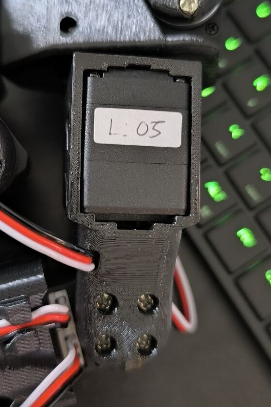
The type of motor can be determined by the label (sticker) on the body. Leader motors often have the gear ratio clearly indicated, whereas Follower motors may not display the gear ratio since they all share the same specification.
2.2. Setting Up the MotorBus
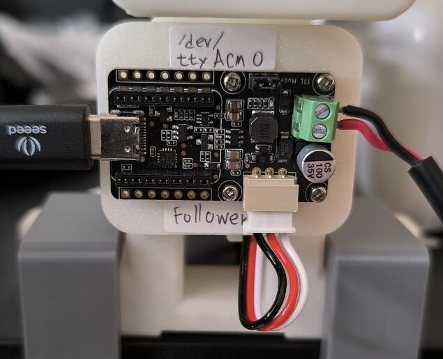
After sorting the motors, set up the MotorBus (see the image below).
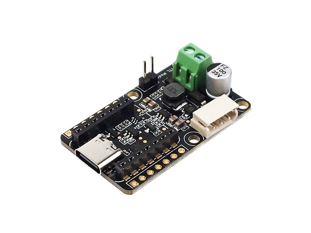
The MotorBus is a device that manages and communicates with multiple motors together.
Prepare one MotorBus for all the Leader motors you sorted in the previous section and one for all the Follower motors. At this stage, if you accidentally mix up the Leader and Follower motors, it will be difficult to correct later, so it's a good idea to label each motor with tack labels or similar to clearly indicate which MotorBus it belongs to.
For convenience in the following steps, we will use these abbreviations:
- Leader MotorBus: Leader_MB
- Follower MotorBus: Follower_MB
-
Power on the Leader_MB and Follower_MB and connect them to your PC.
-
Identify the USB port for each MotorBus.
With both MotorBuses connected, run the following. When prompted during script execution, unplug the USB cable of the Leader_MB and press Enter.
lerobot-find-portExample output:
Finding all available ports for the MotorBus.
['/dev/ttyACM0', '/dev/ttyACM1']
Remove the usb cable from your MotorsBus and press Enter when done.

# (Unplug the cable for Leader_MB and press Enter)

The port of this MotorsBus is /dev/ttyACM0
Reconnect the USB cable.

# (Replug the cable for Leader_MB)
When
Reconnect the USB cable.appears, reattach the Leader_MB cable. In the example above,/dev/ttyACM0is the port for Leader_MB, so record this.
Similarly, unplug the USB cable for the Follower_MB to identify and record the Follower_MB port. In the example above,/dev/ttyACM1is the Follower_MB port number, but note that this may vary depending on your environment.
On Linux, device files may not be recognized due to access permissions, so grant the necessary permissions by running the following if needed. In the example below, we change the permissions of the ttyACM0 device, but note that the device name may vary depending on your environment.
sudo chmod 666 /dev/ttyACM0
2.3. Linking Motors and the MotorBus
The motors are all set to ID 1 by default, so to communicate and synchronize them correctly with the MotorBus, you need to assign a unique ID to each motor. First, to configure the Leader_MB, run the following command:
lerobot-setup-motors \
    --robot.type=so101_follower \
    --robot.port=/dev/ttyACM0 # Leader_MB port number
For --robot.port=, enter the port you identified for the Leader_MB in the MotorBus setup step. If the port you recorded is different from /dev/ttyACM0, replace it accordingly before running.
When communication between the PC and Leader_MB is established, the following message will appear:
Connect the controller board to the '<joint name>' motor only and press enter.
Here, <joint name> indicates the name of the joint that the motor to be assigned the ID is responsible for (e.g., gripper). The steps are as follows:
- Match the motor you prepared in the previous section with the table in that section to prepare the correct type of motor (e.g., for
gripper, use a motor with a 1/147 gear ratio). - Connect that motor to the MotorBus using the motor's cable.
- Press Enter in the terminal.
If the ID assignment is successful, you will see the following:
'<joint name>' motor id set to <ID>
Continue to set IDs for the other Leader motors in the same way. You can see the entire process in the official video below.
After finishing the Leader_MB configuration, similarly configure the Follower_MB. As mentioned above, the Follower motors often all have the same gear ratio, so you don't need to match them to specific joint names. However, be careful not to mix up the IDs you assign.
In the official repository's video, they set the motor IDs after mounting the motors on the arm, but I recommend setting the IDs before mounting them. Since the Leader side is composed of multiple motors with different gear ratios, it's difficult to distinguish them once mounted, and incorrectly mounting one may require disassembly and ID reassignment.
By assigning IDs in advance and labeling the motors (with tack labels, etc.) before assembling them on the arm, you can significantly reduce troubleshooting.
2.4. Assembling the Robot Arm
The assembly steps for the SO-101 are extensive, so first refer to the official tutorial video or the seller's assembly video.
After assembly, be sure to perform motor alignment calibration according to the procedures provided on the official pages or tutorials. Insufficient calibration can cause joint angles to be misaligned, resulting in unexpected postures and potentially dangerous collisions with surrounding objects or people.
For assembly, you can follow either of the videos above, but I have a few tips regarding the servo horn (see image below).
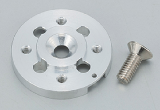
- When attaching the exterior and mechanical parts of the robot arm to the servo horn, use the larger screws. To secure the motor body to the robot arm, use the smaller screws.
- When mounting the servo horn, install it so that the protrusions (tabs) are not visible on the outside (front); flip it so that the flat surface faces outward. If you mount it incorrectly, the screws may not tighten all the way, which can affect the arm's range of motion and smoothness.[2]
3. Operation Check
#Reference link: Imitation Learning on Real-World Robots
Finally, we'll perform an operation check by teleoperating from the Leader to the Follower using the imitation learning sample code provided by LeRobot. Make sure the MotorBus is connected to your PC before running the following command:
lerobot-teleoperate \
    --robot.type=so101_follower \
    --robot.port=/dev/ttyACM0 \ # Enter the port for the Follower_MB as determined in the MotorBus setup
    --robot.id=my_awesome_follower_arm \ # Enter any name you like
    --teleop.type=so101_leader \
    --teleop.port=/dev/ttyttyACM0 \ # Enter the port for the Leader_MB as determined in the MotorBus setup
    --teleop.id=my_awesome_leader_arm # Enter any name you like
If all previous steps were performed correctly, the Follower will follow the Leader's movements as shown in the GIF in the Introduction section.
Conclusion
#This article served as an introduction to Physical AI using LeRobot and SO-101, presenting the environment setup and basic operation verification steps. In the future, given the opportunity, I plan to delve deeper into learning with LeRobot (imitation learning, reinforcement learning) and AI techniques in the robotics domain.