Conceptual Understanding of UseCase Based on UMLspecification ver.2.5.1
Back to TopTo reach a broader audience, this article has been translated from Japanese.
You can find the original version here.
Deep Dive into UML Use Case Diagrams: Interpreting UseCases Conceptually
#1. Introduction: Why Now Deepen Our Conceptual Understanding of UML Use Case Diagrams?
#In system development projects, modeling with UML plays an extremely important role in each phase from requirements definition through design to implementation. In particular, using UseCases is highly effective for establishing a shared understanding among stakeholders and clarifying functional requirements.
However, while UML notation and usage examples are widely known, I believe that conceptual aspects of UML—questions like “Why is it described this way?” and “What semantics underlie this notation?”—and an understanding of its abstract syntax have surprisingly not fully permeated practitioners, myself included. This lack of conceptual understanding directly leads to project risks such as reduced quality of modeling deliverables, misunderstandings, and increased rework.
In this article, we delve into the core concepts of UseCases based on the UML specification (UMLspecification version 2.5.1). By doing so, we aim to improve fundamental UML modeling skills beyond mere mastery of notation. We hope this will help readers produce higher-quality, consistent deliverables in modeling activities during the requirements definition phase.
This article is written based on UMLspecification ver.2.5.1 (hereinafter UMLs), and its content may be partially changed by future UML version revisions. Please note that there may be discrepancies compared to the latest UMLs.
Source:
OMG
2. What is UML: Purpose and Structure of the Unified Modeling Language
#UML stands for “Unified Modeling Language,” and its purpose is to provide system architects, software engineers, and software developers with standard tools for analyzing, designing, and implementing software-based systems, and to support modeling of business processes, among other things.
The UMLs strictly defines the semantics and syntax for using UML as a modeling language, and in order to ensure consistency of model information across different modeling tools, it establishes the following requirements:
- Formal definition of the UML Abstract Syntax: The rules that form the foundation for constructing a complete UML model.
- Detailed explanation of the semantics of each UML modeling concept: The meaning and behavior of each element.
- Concrete Syntax for representing individual UML modeling concepts, that is, the notation elements readable by engineers, and the rules for combining them into various types of diagrams.
In this article, we focus especially on the abstract syntax and semantics described in points 1 and 2, taking a deep dive into Use Case diagrams.
3. Conceptual Understanding of UseCase
#In UML, “UseCase” refers to the conceptual element, while “use case” (e.g., “the customer searches for a product”) refers to the concrete function; we distinguish between them depending on the context.
3.1. Definition and Components of a UseCase
#According to the UMLs, a UseCase has the following characteristics:
- A UseCase is a means of clarifying what a system should do.
- The essential concepts for defining a UseCase are Actor, the use case (the concrete function), and Subject (the system under analysis).
- The Subject refers to the system or scope to which the use case applies or is being considered.
- Actors are described as the users of the target system or “other systems” that may interact with the Subject. Actors can be humans, other systems or devices, or stakeholders playing specific roles.
This concept can be diagrammed as follows:
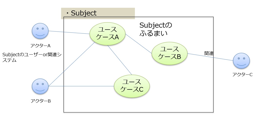
Figure 1: Basic elements and relationships of a Use Case Diagram
3.2. Behavioral Characteristics of Use Cases
#Use cases can apply to any number of Subjects. By applying a use case, the sequence of actions executed by the Subject is articulated, clarifying the interactions with Actors and the resulting outcomes.
Key characteristics of use cases excerpted from the UMLs are as follows:
- A use case is a kind of BehaviorClassifier. This means that a use case is a classifier that defines specific behaviors and that its behavior can be detailed with concrete behavior models (e.g., activity diagrams, sequence diagrams, state machine diagrams).
- Each use case represents a unit of valuable functionality that the Subject provides to the Actor, serving as the primary means of interaction between the Subject and the Actor.
- Each use case specifies behavior that the Subject can execute in cooperation with one or more Actors.
- A use case can include not only normal behavior but also exceptional behavior and error handling.
- To “complete” a use case, all steps defined in that use case must be finished. The completion condition is that, after execution, either (1) the use case becomes executable again, or (2) an error state occurs.
Use cases can be detailed using other UML diagrams such as activity diagrams and state machine diagrams. As needed, preconditions, postconditions, and natural language text can be used, and by combining these with other diagrams, they contribute to a more comprehensive definition of functional requirements.

Figure 2: Use case "Make a Phone Call" and its associated state machine diagram
3.3. Role and Characteristics of Actors
#An Actor is an entity that uses the convenient functions (use cases) that the Subject provides from the outside.
Important characteristics of Actors in the UMLs and their relationship with use cases are as follows:
- An Actor represents an external entity that interacts with the system, playing the role of requesting services from the system or receiving services from it.
- Multiplicity in associations:
- If a use case and an Actor are associated and the multiplicity on the Actor side is greater than 1, it means multiple Actor instances are related to that use case. (For example, in a “Launch Missile” use case, two military officers may need to operate keys simultaneously.)
- If a use case and an Actor are associated and the multiplicity on the use case side is greater than 1, it means a particular Actor can participate in multiple instances of that type of use case.
- An Actor can start multiple use cases concurrently or start them at different times.
4. Relationship between UseCase and Actor in the Abstract Syntax
#The UMLs describe UML from the perspective of its metamodel’s abstract syntax, and particularly, UseCase and Actor form the core elements of Use Case modeling. Based on the UMLs descriptions, we reorganize these concepts.
4.1. UseCase
#- Definition: Represents a unit of functionality that the Subject provides from the perspective of the Actor. It describes a series of interactions that the Subject provides to the Actor.
- Properties:
- Type of Classifier: A classifier that defines a specific type of behavior (function).
- Type of BehaviorClassifier: Specifically, a classifier that defines “behavior,” meaning a use case can be associated with detailed behavioral descriptions (e.g., activity diagrams or sequence diagrams).
- Name: A use case has a unique name, usually in the form “verb + noun” to express a concrete function (e.g., “Add Product to Cart,” “Calculate Deposit”).
- Subject: Indicates the system or component to which the use case belongs. A use case always exists as a function of some Subject.
- OwnedBehavior: A use case can own model elements (e.g., activity diagrams, sequence diagrams) that describe its behavior in detail. This is used to realize the concrete use case description (UC scenario).
4.2. Actor
#- Definition: Refers to an external entity that interacts with the Subject. It plays the role of requesting services from the Subject or receiving services from it.
- Properties:
- Type of Classifier: A concept that defines a collection of objects sharing common characteristics. In this case, it refers to entities playing a specific role.
- Name: Has a proper noun form name (e.g., “HVAC System,” “Customer”).
- Role: Clarifies the boundary between the system (Subject) and the outside, making clear who (or what) interacts with the system and how.
4.3. Relationships between UseCases and Actors
#- Association:
- The most fundamental relationship between an Actor and a use case. It implies that the Actor initiates the use case or receives its results.
- Directionality: An arrow may be added to the association end to indicate the direction of information flow. This is effective when the association is not just a connection but indicates the direction of interaction.
- Multiplicity: Multiplicity can be defined to allow multiplicity in the relationship (e.g., multiple Actor instances involved).
5. Major Relationships between Use Cases
#In use case diagrams, use cases can have complex relationships with each other. The UMLs define two relationships in particular: Extend and Include.
5.1. Extend Relationship
#The Extend relationship indicates a relationship from the extending use case (extension) to the extended use case (base).
- Extend specifies that additional behavior is inserted into the behavior of the extended use case when certain conditions are met.
- This relationship is used when it is necessary to add behavior, possibly conditionally, to behavior defined in one or more use cases.
- The extending use case is defined independently of the extended use case and can be meaningful on its own.
- The extending use case does not necessarily define behavior that is fully meaningful on its own. Rather, it defines a modular set of behaviors that augment the execution of the extended use case under specific conditions.
The UMLs also mention two concepts related to the Extend relationship: ExtensionLocation and ExtensionPoint.

Figure 3: Differences between ExtensionLocation and ExtensionPoint
5.1.1. ExtensionLocation
Specifies the concrete place in the basic flow where, when certain conditions are met, an extension flow is inserted.
Concrete Example of ExtensionLocation (Use Case: Online Shopping)
Basic Flow:
- Customer adds a product to the cart.
- Customer initiates checkout.
- Customer enters shipping information.
- Customer selects a payment method.
- Customer reviews the order.
- Customer confirms the order.
Consider the following extension flows:
- In the case of out-of-stock:
- ExtensionLocation: After Basic Flow step 1 (“Customer adds a product to the cart”)
- Extension Flow:
- The system notifies the customer that the item is out of stock.
- The customer either removes the item from the cart or elects to wait for restock.
- In the case a coupon is applied:
- ExtensionLocation: After Basic Flow step 4 (“Customer selects a payment method”)
- Extension Flow:
- The customer enters a coupon code.
- The system validates the coupon code.
- The system applies the discount.
5.1.2. ExtensionPoint
An ExtensionPoint is a uniquely named location within a use case where behavior can potentially be extended (“If there is an extension, the process may branch at this location”).
Concrete Example of ExtensionPoints (Use Case: Online Shopping)
ExtensionPoints:
- Pre-Stock-Check Processing
- Coupon Application Processing
- Pre-Order Confirmation Processing
Basic Flow:
- Customer adds a product to the cart.
- Pre-Stock-Check Processing
- The system checks stock levels.
- Customer initiates checkout.
- Customer enters shipping information.
- Customer selects a payment method.
- Coupon Application Processing
- Customer reviews the order.
- Pre-Order Confirmation Processing
- Customer confirms the order.
- The system accepts the order.
Note: In this example, “Pre-Stock-Check Processing,” “Coupon Application Processing,” and “Pre-Order Confirmation Processing” are defined as ExtensionPoints.
5.2. Include Relationship
#The Include relationship indicates that the behavior of use case B is inserted into the behavior of use case A (where A is the base use case, and B is the included use case).
5.2.1. Basic Principles of the Include Relationship
The Include relationship indicates that the base use case must execute the behavior of the included use case.
- Reuse of common functionality: Define behaviors that are commonly executed across multiple use cases as separate use cases, and reference them via Include relationships to avoid duplication in use case definitions, improving modeling efficiency and maintainability.
- Clarification of the base use case: Dividing the behavior of a base use case into smaller parts makes the use case description clearer and improves comprehension.
5.2.2. Characteristics of the Include Relationship
- Dependency direction: The base use case depends on the included use case, and the base use case cannot complete without executing the included use case.
- Execution timing: The behavior of the included use case occurs at any specified point during the execution of the base use case.
- Inclusion: The base use case “includes” the behavior of the included use case. That is, the execution of the base use case completes as a single coherent process including the behavior of the included use case.
6. Notation for Use Case Diagrams
#The UMLs also define concrete notations (Concrete Syntax) for drawing use case diagrams.
- UseCase Notation
- Use cases are represented by ellipses.
- The use case’s name is written inside the ellipse or below it.
- If necessary, a stereotype keyword (e.g.,
<<primary>>) is placed above the name.
- Actor Notation
- Actors are represented by stick-figure icons.
- The Actor’s name is usually written above or below the icon.
- Actors can also be represented by rectangular Class notation (see Figure 4).
- Subject (System Boundary) Notation
- The Subject is represented by a rectangle with its name in the top-left corner.
- Use case ellipses are placed within this rectangle.
- If the Subject is a Class with a specific stereotype, the stereotype keyword is placed above its name (see Figure 4).
- Relationship Notation
- Relationships between use cases are represented by dashed arrows.
- For Extend relationships, the arrow points from the extending use case to the extended use case, with the
<<extend>>stereotype on the arrow. - For Include relationships, the arrow points from the base use case to the included use case, with the
<<include>>stereotype on the arrow. - Conditions for Extend relationships and ExtensionPoints are described in note elements and connected with dashed lines (see Figure 4).

Figure 4: Examples of notation in a Use Case diagram
7. Conclusion: From Conceptual Understanding to High-Quality Modeling
#In this article, we explained the abstract syntax, semantics, and major relationships of UseCases based on the UMLs description of use cases. Understanding not only the UML notation but also the conceptual background of “why it is expressed this way” can dramatically improve the quality of UML-based modeling.
Such deep understanding of UML is essential for accurately capturing stakeholder needs and system requirements and translating them into design. We hope this article helps enhance your UML modeling skills and ultimately contributes to the success of your projects.
Going forward, we plan to publish similar articles explaining other chapters of the UMLs (e.g., Activity Diagrams, StateMachine Diagrams) from the same perspective.