Making a Button Battery-Powered Ceiling Light Remote Control Using ATtiny13A [Preparation Edition]
Back to TopTo reach a broader audience, this article has been translated from Japanese.
You can find the original version here.
Over the past year, I’ve been developing at work using C#. With an abundant development environment and plentiful CPU and memory resources, I stopped obsessing over speed and memory efficiency and instead embraced 「富豪的プログラミング」 for development.
On the other hand, in my personal time I’ve enjoyed various electronics projects with Arduino. And then I thought,
"You're not even using the full potential of the microcontroller’s specs!"
These single-chip microcontrollers that practically fit in the palm—until now, I didn’t really worry about speed, program size, data size, etc. I always had plenty of spare pins available and only used one or two of the built-in functions, so there was never that feeling of having pushed the performance to its limit. In a way, I was also practicing "富豪的プログラミング" with Arduino.
So this time, in defiance of that approach, I decided to take on the challenge of creating a remote control for a ceiling light (LED lighting) with the theme:
"Push the hardware’s performance to the limit and build something useful on a tight budget."
Since the article has grown quite lengthy, I’ve divided it into [Preparation Edition], [Development Edition], and [PCB/Case Creation Edition]. This article serves as a record of the process and my approach.
ATtiny13A Overview
#There are various Arduino models available—for example, the Arduino Uno R3 uses a microcontroller called the ATMega328P. “AT” comes from Atmel, the company that developed the microcontroller [1], and “Mega” likely implies something big. So, even though we call it a microcontroller, its CPU is “mega.” When I looked for something even smaller (Tiny) that could be used in the Arduino development environment, I found the ATtiny13A.
Main Specifications of ATtiny13A
#Here are some excerpts from the ATtiny13A datasheet [2]:
| Item | Specification / Overview |
|---|---|
| CPU | AVR 8-bit microcontroller |
| Clock | Up to 20MHz |
| Operating Voltage | 1.8-5.5V |
| Flash Memory | Non-volatile memory (high-speed, high capacity) 1024 Bytes (for program storage) |
| EEPROM | Non-volatile memory (low-speed, small capacity) 64 Bytes (for data storage) |
| SRAM | Volatile memory (high-speed) 64 Bytes (working memory) |
| Timer | One 8-bit timer |
| Analog-to-Digital Conversion | 4-channel 10-bit |
AVR microcontrollers use a Harvard architecture, which means that program instructions and data are physically separated. Therefore, it is necessary to keep both program size and data size in mind when coding.
Since the ATtiny13A operates at 1.8V, it can be run on a button battery (3V). However, you only have 1024 Bytes of flash memory for the program and 64 Bytes of SRAM for data. The challenge is to write the program within these strict limits.
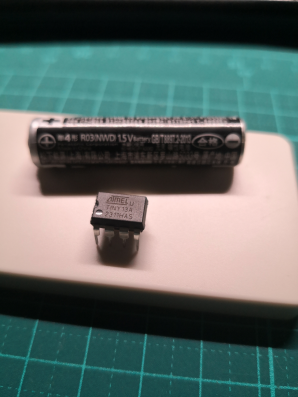
By the way, the top image was taken with a AAA battery next to the ATtiny13A to illustrate its size. The image file is 135 KByte (139190 Bytes), which is about 135 times the size of the ATtiny13A’s 1024 Byte flash memory. I was a bit anxious about whether I could fit the remote control’s program into just 1024 Bytes.
The program is written in C or C++ (assembly is also possible). With only 64 Bytes of SRAM, you can only store 64 ASCII characters of string data, so inserting debug messages consumes both program space and data space, making them impractical. Moreover, the hardware does not support debug output (UART) at all 🫠
Pin Layout
#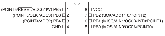
There are 8 pins, numbered 1 to 8 in counterclockwise order starting from the top left. Pin 8 is for power and pin 4 is connected to GND, leaving pins 1–3 and 5–7 (a total of 6 pins) available for other functions. Each pin corresponds to an I/O port (PB0 to PB5, six in total) and can also be assigned one of the functions indicated above.
For example, pin 6 can serve as INT0, which is used for external interrupts. By connecting a switch or button to pin 6, an external interrupt handler (a function) can be called when its state changes. Additionally, ADC0 to ADC3 are available on the respective pins; ADC is a function that reads an analog voltage and converts it to a 10-bit (1024 levels) value.
Note that the functions available vary from pin to pin.
While it would be simple to set things up using the Arduino API, using it on the ATtiny13A would greatly increase the program size—soon surpassing the 1024 Byte limit—so it isn’t practical. Therefore, I end up assigning functions by directly manipulating registers.
Register Operations
#Registers are areas within the microcontroller that hold its state or are used to change pin assignments, and you can reference or set these registers from your program (whether in C, C++, or assembly). From the program’s perspective, they look like ordinary variables (pointers to memory addresses).
Example registers:
| Register | Name | Description |
|---|---|---|
| DDRB | Port B Data Direction | Configures whether the port is an input or an output |
| PORTB | Port B Output | Sets the ON/OFF state of the port |
| TCCR0A | Timer/Counter Control Register A | Controls the timer/counter |
| OCR0A | Timer/Counter Compare Register A | Sets the comparison value for the timer/counter |
| PRR | Power Reduction Register | Settings related to power reduction |
| GIMSK | General Interrupt Mask Register | Settings related to interrupt enabling |
| PCMSK | Pin Change Mask Register | Settings related to pin change interrupts |
Directly manipulating registers can reduce the program size and allow for low-level operations. On the downside, it makes the code highly dependent on the specific microcontroller, and you have to spend extra time poring over the datasheet.
Each microcontroller has its own pin layout and registers. The Arduino API abstracts these differences in register operations, enabling you to control various microcontrollers with the same functions. A drawback is that the header files contain many preprocessor directives (#if, #ifdef, #define), which can be confusing.
Communication Format
#There are several standards for infrared transmission, and many manufacturers follow one of these standards when transmitting IR signals. In Japan, the NEC format, the 家製協 format, and the SONY format are commonly used.
To better understand these communication formats, I referred to the following websites:
通信フォーマット
赤外線リモコンのフォーマット
赤外線リモコンの信号定義データの合成
38KHz変調のパルス送信イメージ
When I checked the model number on the ceiling light remote control in the living room, it turned out to be Panasonic HK9493. It was necessary to determine which communication format this remote control uses for IR transmission.
Preparing the Development Environment
#Settings for Developing with the Arduino IDE
#To develop for the ATtiny13A using the Arduino IDE, the following are required:
- MicroCore as the Board Manager
- A programmer for uploading the sketch (I used an Arduino Uno)
For details on the board manager and installation, please refer to:
I am using Arduino IDE 1.8.19 because it is an established asset. It is unknown whether it works with Arduino IDE 2.X.X.
Analysis of Infrared Transmission Data
#Now, how can one obtain the infrared transmission data? The manufacturer’s website does not publish this information. You need to capture the IR data transmitted by an actual remote control using an infrared receiver module, and then deduce the communication format from that data.
Arduino offers an abundance of excellent open-source libraries. There’s one called IRremote for sending and receiving infrared data, and I used it to analyze the data.
I purchased the infrared remote control receiver module OSRB38C9AA from Akizuki Denshi. Using the application example from the datasheet [3], I quickly assembled a circuit on a breadboard.
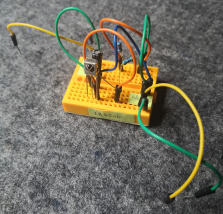
The yellow line on the left is the output that sends the received infrared data, the yellow line on the right supplies power, and the green line is GND. The upright, three-legged component is the infrared remote control receiver module.
Skipping over some of the details, I wrote the following sketch in Arduino and connected it to the breadboard:
#include <IRremote.h>

int receiverPin = 8;

void setup() {
    Serial.begin(9600);
    IrReceiver.begin(receiverPin, true);
}

void loop() {
    if (IrReceiver.decode()) {
        // Display the code for sending the received signal
        IrReceiver.printIRSendUsage(&Serial);
        // Display the result in RAW format
        IrReceiver.printIRResultRawFormatted(&Serial, true);
        IrReceiver.resume();
    }
}
When you point the remote control at the IR receiver module and transmit an infrared signal, you’ll see output like the following:
uint32_t tRawData[]={0x9939522C, 0xA0};
IrSender.sendPulseDistanceWidthFromArray(38, 3450, 1700, 450, 1300,
        450, 450, &tRawData[0], 40, PROTOCOL_IS_LSB_FIRST,
        <RepeatPeriodMillis>, <numberOfRepeats>);
 -3276750
 +3450,-1700
 + 450,- 400 + 450,- 400 + 450,-1300 + 400,-1300
 + 450,- 400 + 450,-1250 + 450,- 450 + 400,- 450
 + 400,- 450 + 450,-1250 + 450,- 400 + 400,- 450
 + 450,-1300 + 400,- 450 + 450,-1250 + 450,- 400
 + 450,-1250 + 450,- 450 + 400,- 450 + 400,-1300
 + 400,-1300 + 450,-1300 + 400,- 450 + 400,- 450
 + 400,-1300 + 450,- 400 + 450,- 450 + 400,-1300
 + 450,-1250 + 450,- 400 + 450,- 400 + 450,-1300
 + 400,- 450 + 400,- 450 + 400,- 450 + 450,- 400
 + 400,- 450 + 450,-1300 + 400,- 450 + 400,-1300
 + 450
Sum: 53600
uint32_t tRawData[]={0x9939522C, 0xA0};- 0x9939522C is the received data
- 0xA0 is the parity
- Explanation of the arguments for
IrSender.sendPulseDistanceWidthFromArray():void IRsend::sendPulseDistanceWidthFromArray( // Frequency [kHz] uint_fast8_t aFrequencyKHz, // Header: transmission ON duration [usec] uint16_t aHeaderMarkMicros, // Header: transmission OFF duration [usec] uint16_t aHeaderSpaceMicros, // Data: transmission ON duration when sending bit value 1 [usec] uint16_t aOneMarkMicros, // Data: waiting time after transmission when sending bit value 1 [usec] uint16_t aOneSpaceMicros, // Data: transmission ON duration when sending bit value 0 [usec] uint16_t aZeroMarkMicros, // Data: waiting time after transmission when sending bit value 0 [usec] uint16_t aZeroSpaceMicros, // Array of transmission data IRRawDataType *aDecodedRawDataArray, // Number of bits for header part transmission uint16_t aNumberOfBits, // Bit transmission order uint8_t aFlags, // Waiting time during repeat uint16_t aRepeatPeriodMillis, // Number of repeats int_fast8_t aNumberOfRepeats ) - The sequence of + and – numbers represents the received durations for bit values (0 or 1) and is used to calculate the arguments for the function IrSender.sendPulseDistanceWidthFromArray.
- A “+” represents the duration when the bit value is received (ON) [usec]
- A “–” represents the duration when the bit value is not received (OFF) [usec]
You can see that the “+” and “–” values alternate at regular intervals.
Since the header’s ON/OFF durations are given as +3450 (8T) and –1700 (4T), and the data part’s ON duration is +450 (1T), it is clear that this is the 家製協フォーマット.
In the central section, where the “+ and – come in pairs:
- A pair where “+” is between 400 and 450 and “–” is also between 400 and 450 is interpreted as 0.
- A pair where “+” is between 400 and 450 and “–” is between 1250 and 1300 is interpreted as 1.
If you convert these into binary and then represent the value read from the least significant bit (LSB) in hexadecimal, you get the following:
 (+xxx, -xxx)(+xxx, -xxx)(+xxx, -xxx)(+xxx, -xxx)    Binary  Hex
 + 450,- 400 + 450,- 400 + 450,-1300 + 400,-1300  →  0011    C
 + 450,- 400 + 450,-1250 + 450,- 450 + 400,- 450  →  0100    2
 + 400,- 450 + 450,-1250 + 450,- 400 + 400,- 450  →  0100    2
 + 450,-1300 + 400,- 450 + 450,-1250 + 450,- 400  →  1010    5
 + 450,-1250 + 450,- 450 + 400,- 450 + 400,-1300  →  1001    9
 + 400,-1300 + 450,-1300 + 400,- 450 + 400,- 450  →  1100    3
 + 400,-1300 + 450,- 400 + 450,- 450 + 400,-1300  →  1001    9
 + 450,-1250 + 450,- 400 + 450,- 400 + 450,-1300  →  1001    9
 + 400,- 450 + 400,- 450 + 400,- 450 + 450,- 400  →  0000    0
 + 400,- 450 + 450,-1300 + 400,- 450 + 400,-1300  →  0101    A
These values correspond to the earlier data in uint32_t tRawData[]={0x9939522C, 0xA0};. When reading 0x9939522C bit by bit from the LSB, the value matches, indicating that after transmitting the data the parity 0xA0 is sent in LSB order.
Ultimately, the transmission is performed with 38KHz modulation as follows:
- Header transmission (signaling that data is about to be sent)
- Transmit a 1 using the duration given by the 2nd argument of IRsend::sendPulseDistanceWidthFromArray, and a 0 using the 3rd argument.
- Data transmission
- Transmit 0x9939522C using the time intervals from the 4th to the 7th arguments of IRsend::sendPulseDistanceWidthFromArray, sending the bits in LSB (least significant bit) order.
- Parity check value transmission
- Transmit 0xA0 in LSB order.
- Use the same time intervals as for data transmission.
- Trailer transmission (signaling that data transmission is complete)
The key point is that when transmitting a 1, it isn’t as simple as turning the IR LED on for 450 [usec] and then off for 1300 [usec]; instead, during the “on” period the LED is pulsed at a 38KHz frequency. In other words, at 38KHz (with a cycle of roughly 26 [usec], toggling every 13 [usec]), the LED is turned on and off repeatedly for 450 [usec].
Achieving microsecond-level control on operating systems like Windows or Linux is extremely difficult (if not impossible). It’s quite moving that this is possible with a microcontroller that costs only 160 yen [4].
Debugging Using Serial Communication
#The ATtiny13A does not have a hardware UART, so checking the state of the program is challenging. I resort to simple methods such as indicating status via LED blinking. While it is possible to create a software UART library, dedicating two pins (one for input and one for output) solely for debugging is problematic. Additionally, a UART library can quickly bloat the program size.
UART is an asynchronous, full-duplex serial data communication method. Arduino handles UART in hardware. When debugging microcontroller programs, it’s common to connect to the UART and use terminal software to view output.
To address these issues, an excellent library by Nerd Ralph was released.
It is an assembly-written library called BasicSerial3 that uses only one pin for half-duplex serial communication on the ATtiny. It’s a mere 62 Bytes. Unfortunately, the original link was broken, so I obtained BasicSerial3 from another site and used it.
- Although a new alternative called picoUART has been released, it has been rewritten from assembly to C++, roughly doubling the ROM usage.
- BasicSerial3 was sufficient for my needs, so I found and used a GitHub project that utilizes BasicSerial3.
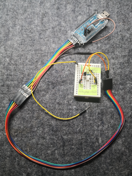
The white breadboard houses the serial communication circuit. A single yellow wire is connected to the ATtiny13A’s PB3 (pin 2), and the baud rate is set to 115200. The orange and yellow wires are connected to the TX/RX of a USB-Serial Converter Adapter; when you connect the USB to a PC, you can view the output with terminal software like Tera Term.
Since this USB-Serial Converter Adapter supports the DTR signal, it’s very handy for uploading sketches to homemade Arduino-compatible devices.
Then, by creating functions for string output and numeric output as shown below, you can perform UART output simply by calling them.
// Output string
void serOut(const char* str) {
    while (*str) {TxByte (*str++);}
}

// Output integer in decimal
void OutDEC(uint16_t d) {
    int8_t n = -1;
    uint16_t v = 10000;
    for (uint8_t i = 0; i < 5; i++) {
        if (d >= v) {
            TxByte(d / v + '0');
            d %= v;
            n = i;
        } else {
            if (n != -1 || i == 4) TxByte('0');
        }
        v /= 10;
    }
}
Summary
#After spending a considerable amount of time researching, gathering parts, and building test circuits and programs, I’ve now acquired almost all the know-how needed to build the remote control. Although nothing tangible yet, I’ve gained the feeling that it can be done.
Next time, I’ll move on to the Development Edition.