Building an Oscilloscope with Raspberry Pi Pico and Android Smartphone
Back to TopTo reach a broader audience, this article has been translated from Japanese.
You can find the original version here.
Previously, I introduced how to debug the Raspberry Pi Pico using a Raspberry Pi Debug Probe and Platform IO.
This time, I would like to try building a simple oscilloscope using the Raspberry Pi Pico and an Android smartphone.
What is Raspberry Pi Pico?
#The Raspberry Pi series are single-board computers equipped with ARM processors.
The most recently released model is probably the Model 5.
Models 5 and 4 are equipped with HDMI and USB ports, and a microSD card slot, and can be used as a PC by installing an OS on a microSD card, making them high-performance single-board computers.
In contrast, the "Raspberry Pi Pico" looks like the following and is closer to embedded development boards like the ESP32 or Arduino Nano.
Raspberry Pi Pico appearance
(The one in the photo is the H type, which comes pre-equipped with a JST 3-pin SH connector on the debug terminal and soldered pin headers)

While it's not suited for high-functionality applications like the Model 5 or Model 4, the Raspberry Pi Pico (hereafter referred to as "Pico") is affordable and suitable for electronic projects. (Reference: Switch Science)
What is an Oscilloscope?
#An oscilloscope is a measuring instrument that visually displays the waveform of an input electrical signal.
Generally, it displays the input signal waveform on the vertical axis and time on the horizontal axis.
Recently, relatively inexpensive oscilloscopes have been sold on Amazon, but even though they have become cheaper, they still cost around ten thousand yen, so it's not something you'd buy on a whim.
Wanting to Check Signal Waveforms When Building PWM Control Circuits or Oscillator Circuits
#While I don't think there are many occasions for the average electronics hobbyist to use an oscilloscope, there are times when you want to check the signal waveform when creating motor PWM control circuits or oscillator circuits.
So, this time, I would like to introduce a handy app that turns an "Android smartphone" into an oscilloscope.
Scoppy - Oscilloscope and Logic Analyzer
#The app we're introducing this time is Scoppy - Oscilloscope and Logic Analyzer.
Install this app on your Android smartphone.
Next, prepare the Pico, and download the firmware for the Pico from here and install it on the Pico.
(To install the firmware, connect the Pico to a PC with a MicroUSB connector while pressing the button on the Pico board. The Pico will boot in BOOTSEL mode, and the PC will mount the Pico as storage, so you drag the firmware file to the Pico to write it.)
I was going to write detailed instructions, but I found a video that explains how to install the app, write the firmware to the Pico, and design the circuit (Pico + a few resistors), so I will introduce it.
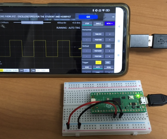
Follow the video to connect the Pico and smartphone and perform a self-operation check.
Connect GPIO 22 directly to the ADC pin (GPIO 26) and display the test signal on GPIO 22.
GPIO 22 is a square wave with a 50% duty cycle at 1kHz.
The video mentioned above shows how to wire the input voltage range from minus 5V to plus 5V, but I took a shortcut and made it so that it can only measure within the range of 0V to 3.3V, as introduced in this video.
This method only requires three resistors (100kΩ×1, 10kΩ×2).
Operation Check of the Oscilloscope Using the PWM Module
#Let's do an operation check using the "PWM Module" that was also used in the video I mentioned earlier.
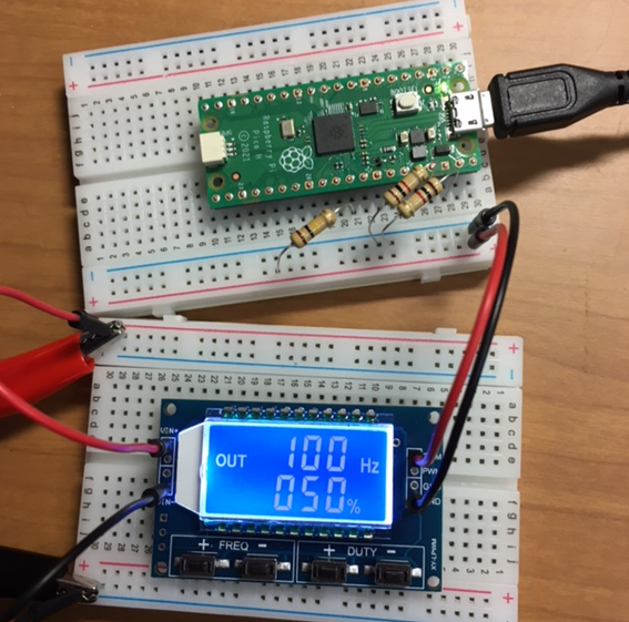
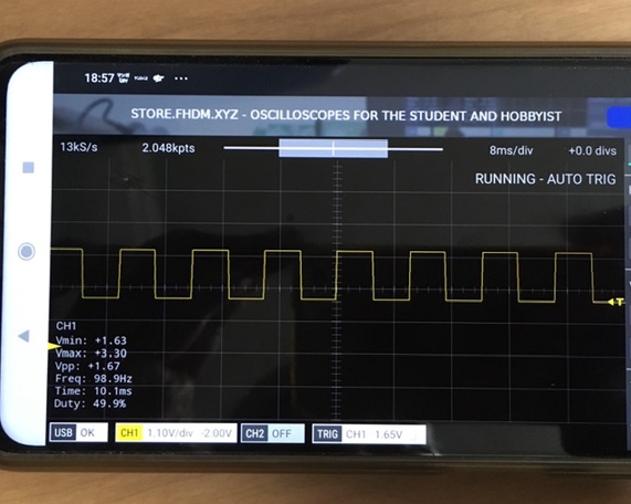
Let's generate a signal with a 50% duty cycle at 100Hz.
The signal waveform was displayed on Scoppy (smartphone oscilloscope) as follows.
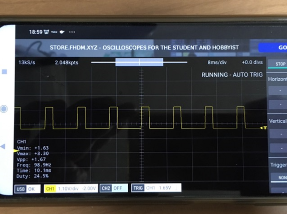
Next, let's generate signals by changing the duty cycle to 25% and 75%.
In the case of 25%
In the case of 75%
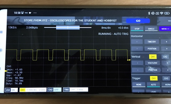
There is some margin of error, but it seems to be capturing the signal waveform correctly.
Conclusion
#This time, we were able to build an oscilloscope by installing "Scoppy - Oscilloscope and Logic Analyzer" on a Raspberry Pi Pico and an Android smartphone.
With the current circuit, you can only measure signal waveforms from 0V to 3.3V, but it seems you can measure signal waveforms beyond that limit by using this board.
It comes as a kit, but you can get an oscilloscope much cheaper than buying a commercial product.
(If you use Scoppy for free, the number of channels available is limited to one channel.)
Why not give it a try?