Debugging the STM32 Microcontroller Board (STM32F103C8T6) with a ST-Link V2 Clone and Platform IO
Back to TopTo reach a broader audience, this article has been translated from Japanese.
You can find the original version here.
In previous articles related to microcontroller boards, I have discussed ESP32, Arduino, and Raspberry Pi. Apart from these well-known families, the "STM32" family of microcontroller boards is also fairly popular. This time, I would like to use the affordable and readily available "STM32F103C8T6" microcontroller board to implement a program to blink an LED (referred to as "L Chika") and execute debugging of the L Chika program.
What is STM32?
#The STM32 family consists of 32-bit general-purpose microcontrollers manufactured and sold by STMicroelectronics, equipped with the Arm Cortex-M series. Since the CPU is ARM, it can utilize various applications created for ARM. There is also an 8-bit "STM8" family.
Affordable Microcontroller Board "STM32F103C8T6"
#The microcontroller board we are using this time is the "STM32F103C8T6". It is often referred to as the "Blue Pill" and is sold at a very low price on Amazon. It can be obtained even cheaper on AliExpress, though it takes longer to deliver. It turned out that the microcontroller board I purchased this time was a clone.
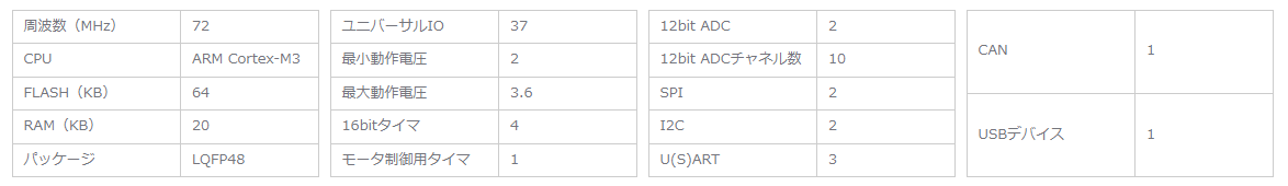
There is a wide range of products in the STM32 family. Please refer to the product homepage for information on the CPU and memory of the "STM32F103C8T6" we are using this time.
Product specifications:
Appearance (with soldered pin headers):
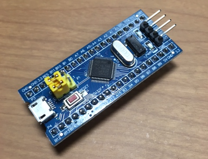
Like the ESP32, Arduino Nano, and Raspberry Pi Pico, it comes in a package intended for embedded applications. There are two jumper pins on the top of the body, each of which can be set to "0" or "1".
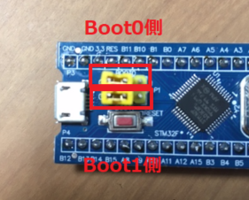
Normally, it is used with the settings "Boot0:0, Boot1:0". When programming via serial communication pins, it seems that it should be set to "Boot0:1, Boot1:0". (This time, as mentioned later, we will perform the writing using a device called ST-Link, so the settings will remain normal.)
ST-Link V2 Clone
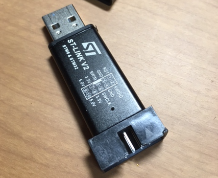
#Since the genuine ST-Link is expensive, we will use a clone (laughs). We purchased the ST-Link V2 compatible programmer (hereafter referred to as ST-Link) as shown in the image below. It can be obtained at a low price from Amazon. It is even cheaper on AliExpress.
To use ST-Link on a PC, you need a driver for ST-Link. Download the driver from the following URL.
(It seems that you can download it as a guest without registering as a user.)
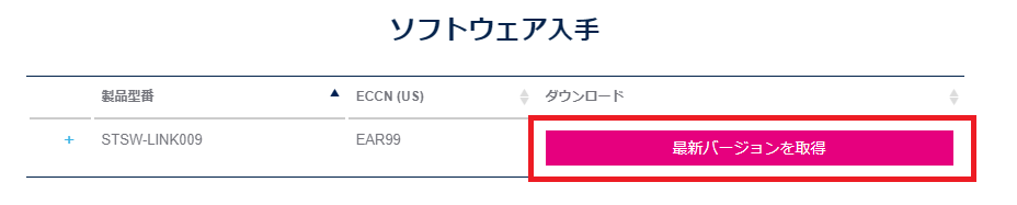
The file "en.stsw-link009.zip" will be downloaded from the above URL, so unzip the Zip file and run "dpinst_amd64.exe" (for 64-bit PCs) included in the unzipped folder to install the driver.
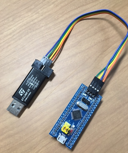
Connecting ST-Link and STM32F103C8T6
#Connect ST-Link and STM32F103C8T6 (hereafter referred to as STM32) as follows.
| ST-Link | STM32 |
|---|---|
| SWDIO | SWO |
| GND | GND |
| SWCLK | SWCLK |
| 3.3V | 3.3V |
(The terminal marked "SWO" on the STM32 side is believed to be "SWDIO").
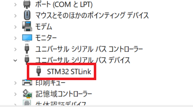
After installing the ST-Link driver, connect ST-Link to the USB port of the PC and check that ST-Link is recognized in the Device Manager. If it is displayed as follows, the driver has been successfully installed.
ST-Link Firmware Upgrade
#It may not be mandatory, but we will upgrade the firmware of ST-Link (other sites referring to ST-Link information recommended upgrading the firmware).
Download the utility called "STM32 ST-LINK Utility" and upgrade the firmware of ST-Link. Download the utility from the following URL.
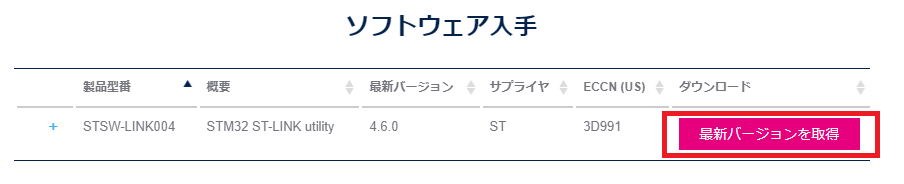
The file "en.stsw-link004.zip" will be downloaded from the above URL, so unzip the Zip file and run "setup.exe" included in the unzipped folder to install the utility.
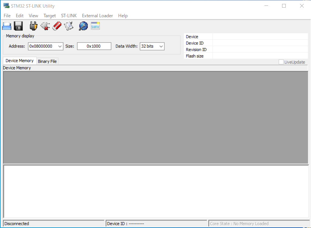
Run the installed STM32 ST-LINK Utility. The following application will start.
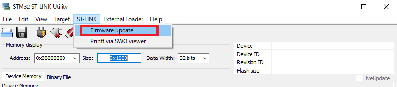
Click "ST-LINK" - "Firmware update".
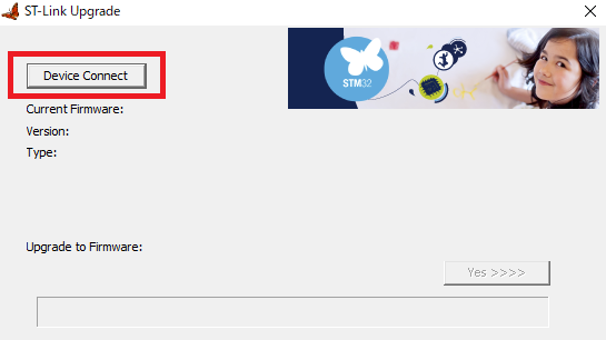
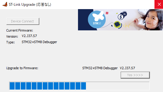
When the ST-Link Upgrade dialog appears, click "Device Connect".
Once the device is connected, click "YES" on the right side of Upgrade to Firmware.
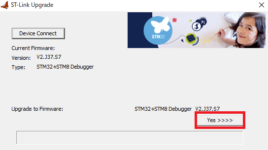
The firmware upgrade will begin.
(In my case, the firmware had already been upgraded, so the version in the image remains the same after the upgrade.)
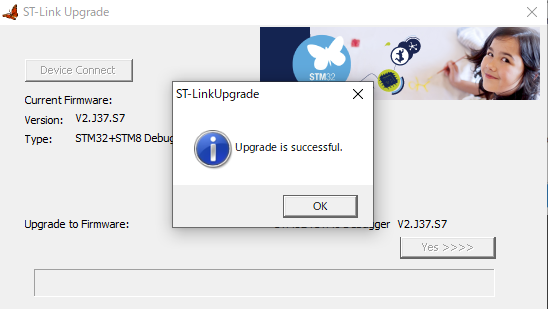
The upgrade is complete.
Installation of STM32CubeProg
#Actually, the utility download page mentioned earlier also mentioned the recommended product "STM32CubeProg".
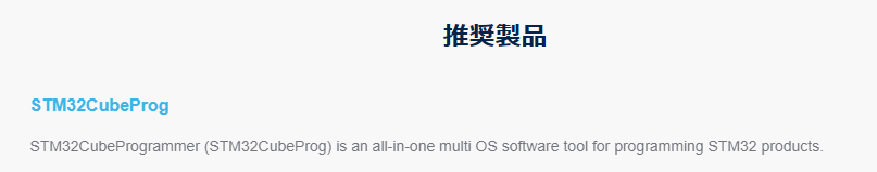
STM32CubeProg does not seem to support ST-Link V2 clones, but since the "Arduino IDE" used in the latter part of this article is set to use the command line utility included in this utility, let's install it now.
Download STM32CubeProg from the following URL.
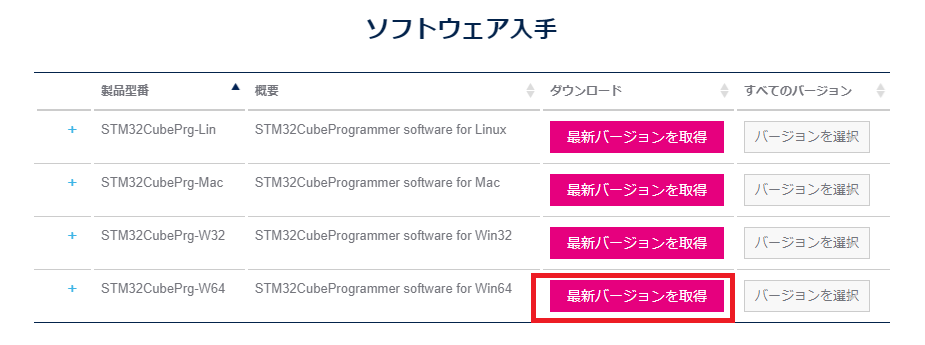
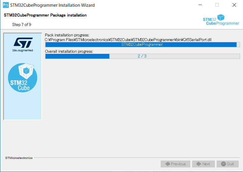
The file "en.stm32cubeprg-win64-v2-15-0.zip" (as of 2024-01-27) will be downloaded from the above URL, so unzip the Zip file and run "SetupSTM32CubeProgrammer_win64.exe" included in the unzipped folder to install the utility.
Proceed with the installation. Several option settings are confirmed during the installation, but install with all default settings.
Preparing Arduino IDE (STM32 Board Information)
#We will use the "Arduino IDE" that has been used in previous microcontroller board articles to write, build, and write programs.
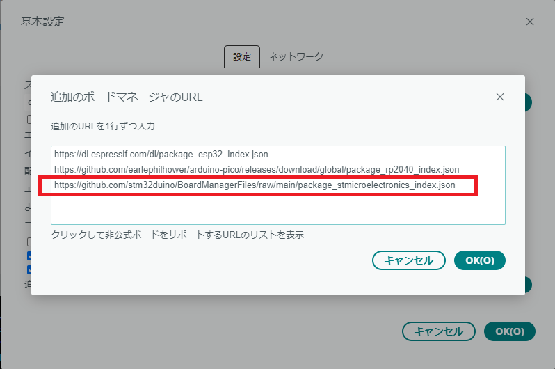
First, add the URL of the STM32 board manager to the basic settings of Arduino IDE (V2.2.1). The URL to add is as follows:
https://github.com/stm32duino/BoardManagerFiles/raw/main/package_stmicroelectronics_index.json
Add the above URL to the "Additional Board Managers" in the basic settings.
"STM32 MCU based boards" will be displayed in the Arduino IDE board manager as shown below, so install it. (It takes quite a while.)
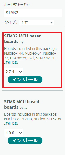
Once the installation is complete, "STM32 MCU based boards" should be added to the board manager's board list.
Creating an STM32 Project in Arduino IDE
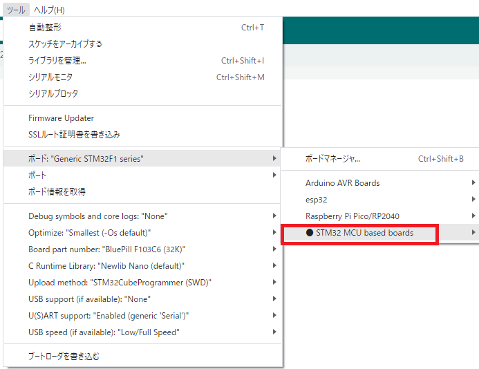
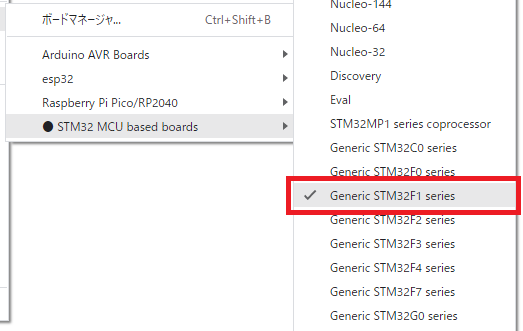
#Select the "Generic STM32F1 series" board in the Arduino IDE board manager.
Change the board settings as follows.
(The COM port is not used this time, so it doesn't matter what is selected.)
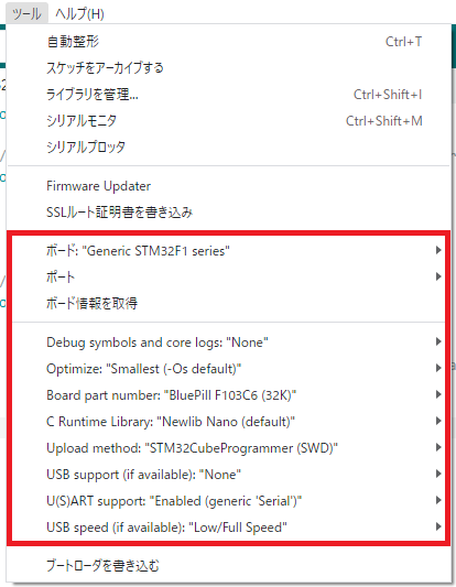
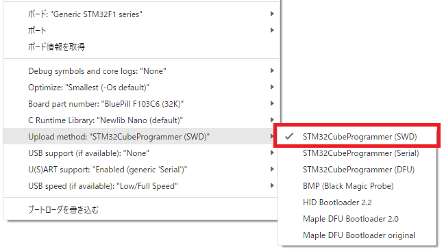
Make sure that "Upload method" is set to "STM32CubeProgrammer(SWD)".
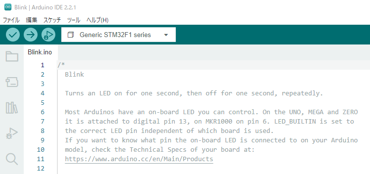
Select "Blink" from "File" - "Sketch Example" - "0.Basics".
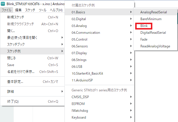
The default Blink project is created.
Creating an L Chika Program (for STM32F103C8T6)
#I created an L Chika (LED blinking) program as follows.
const int T_DELAY = 1000;

// the setup function runs once when you press reset or power the board
void setup() {
  // initialize digital pin PC13 as an output.
  pinMode(PC13, OUTPUT);
}

// the loop function runs over and over again forever
void loop() {
  digitalWrite(PC13, HIGH);   // turn the LED on (HIGH is the voltage level)
  delay(T_DELAY);             // wait for a second
  digitalWrite(PC13, LOW);    // turn the LED off by making the voltage LOW
  delay(T_DELAY);             // wait for a second
}
The output terminal for blinking the LED is specified as "PC13".
(Please be careful, as this is a part that is often mistaken.)
Writing the Program from Arduino IDE
#Write the program from Arduino IDE.
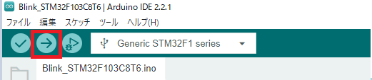
The following message was output. It can be seen that the program has been written to the STM32 and executed successfully.
Maximum 32768 bytes of flash memory, of which the sketch uses 18056 bytes (55%).
Maximum 10240 bytes of RAM, of which global variables use 1256 bytes (12%), and local variables can use 8984 bytes.
      -------------------------------------------------------------------
                       STM32CubeProgrammer v2.15.0
      -------------------------------------------------------------------

ST-LINK SN  : 9
ST-LINK FW  : V2J37S7
Board       : --
Voltage     : 3.23V
SWD freq    : 4000 KHz
Connect mode: Under Reset
Reset mode  : Hardware reset
Device ID   : 0x410
Revision ID : Rev X
Device name : STM32F101/F102/F103 Medium-density
Flash size  : 128 KBytes
Device type : MCU
Device CPU  : Cortex-M3
BL Version  : --

Memory Programming ...
Opening and parsing file: Blink_STM32F103C8T6.ino.bin
  File          : Blink_STM32F103C8T6.ino.bin
  Size          : 17.92 KB
  Address       : 0x08000000

Erasing memory corresponding to segment 0:
Erasing internal memory sectors [0 17]
Download in Progress:

File download complete
Time elapsed during download operation: 00:00:00.475

RUNNING Program ...
  Address:      : 0x8000000
Application is running, Please Hold on...
Start operation achieved successfully
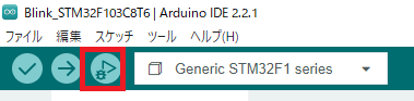
Error Occurred When Executing Debug from Arduino IDE
#I tried executing debug from Arduino IDE.
The following message was output.
Licensed under GNU GPL v2
For bug reports, read
        http://openocd.org/doc/doxygen/bugs.html
CDRTOSConfigure
Info : The selected transport took over low-level target control. The results might differ compared to plain JTAG/SWD
srst_only separate srst_nogate srst_open_drain connect_deassert_srst

Info : Listening on port 50001 for tcl connections
Info : Listening on port 50002 for telnet connections
Info : clock speed 1000 kHz
Info : STLINK V2J37S7 (API v2) VID:PID 0483:3748
Info : Target voltage: 3.225296
Warn : UNEXPECTED idcode: 0x2ba01477
Error: expected 1 of 1: 0x1ba01477

[2024-01-28T01:35:54.260Z] SERVER CONSOLE DEBUG: onBackendConnect: gdb-server session closed
GDB server session ended. This terminal will be reused, waiting for next session to start...
It seems to be an error where the expected code is not found in the "idcode" part.
Warn : UNEXPECTED idcode: 0x2ba01477
Error: expected 1 of 1: 0x1ba01477
I will give up on debugging with Arduino IDE for now and will check debugging on the Platform IO side.
Creating an STM32 Project in Platform IO
#I would like to use Platform IO, which I have used before, to write, execute, and debug programs.
(For setup of Platform IO, please refer to the previously written article "Trying IoT (Part 14: OLED SSD1306 Edition)").
Create an STM32 project in Platform IO.
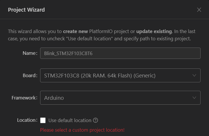
- Project Name: "Blink_STM32F103C8T6" (← you can name it whatever you like)
- Board: "STM32F103C8 (20k RAM. 64k Flash)(Generic)"
- Framework: "Arduino"
- Location: Check OFF (do not use the default location)
After the project is created, check the platformio.ini file.
The upload protocol seems to be ST-Link by default, so the description is omitted.
[env:genericSTM32F103C8]
platform = ststm32
board = genericSTM32F103C8
framework = arduino
Writing the Program from Platform IO
#Write the same program as executed in Arduino IDE into main.cpp.
However, I included the header file "Arduino.h" at the beginning of the source code.
#include <Arduino.h>
When I executed the program writing from Platform IO, the following error occurred.
Advanced Memory Usage is available via "PlatformIO Home > Project Inspect"
RAM:   [=         ]   5.5% (used 1132 bytes from 20480 bytes)
Flash: [==        ]  16.6% (used 10872 bytes from 65536 bytes)
Configuring upload protocol...
AVAILABLE: blackmagic, cmsis-dap, dfu, jlink, serial, stlink
CURRENT: upload_protocol = stlink
Uploading .pio\build\genericSTM32F103C8\firmware.elf
xPack Open On-Chip Debugger 0.12.0-01004-g9ea7f3d64-dirty (2023-01-30-15:04)
Licensed under GNU GPL v2
For bug reports, read
        http://openocd.org/doc/doxygen/bugs.html
debug_level: 1

hla_swd
Warn : UNEXPECTED idcode: 0x2ba01477
Error: expected 1 of 1: 0x1ba01477
in procedure 'program'
** OpenOCD init failed **
shutdown command invoked

*** [upload] Error 1
The error that occurred in the debugging part of the Arduino IDE seems similar.
I researched the above error content and was able to obtain information from the following URL.
It seems that the purchased STM32 is a clone product (CS32F103C8T6 chip instead of STM32F103C8T6), so additional settings like the following are necessary.
I modified the platformio.ini file as follows.
[env:genericSTM32F103C8]
platform = ststm32
board = genericSTM32F103C8
framework = arduino
upload_flags = -c set CPUTAPID 0x2ba01477
Change the settings and write the program again.
Advanced Memory Usage is available via "PlatformIO Home > Project Inspect"
RAM: [= ] 5.5% (used 1132 bytes from 20480 bytes)
Flash: [== ],16.6% (used 10872 bytes from 65536 bytes)
Configuring upload protocol...
AVAILABLE: blackmagic, cmsis-dap, dfu, jlink, serial, stlink
CURRENT: upload_protocol = stlink
Uploading .pio\build\genericSTM32F103C8\firmware.elf
xPack Open On-Chip Debugger 0.12.0-01004-g9ea7f3d64-dirty (2023-01-30-15:04)
Licensed under GNU GPL v2
For bug reports, read
http://openocd.org/doc/doxygen/bugs.html
debug_level: 1
0x2ba01477
hla_swd
[stm32f1x.cpu] halted due to debug-request, current mode: Thread
xPSR: 0x01000000 pc: 0x080001a4 msp: 0x20005000
** Programming Started **
Warn : Adding extra erase range, 0x08002b9c .. 0x08002bff
** Programming Finished **
** Verify Started **
** Verified OK **
** Resetting Target **
shutdown command invoked
The program writing was successful. The LED was able to blink at the set interval.
## Debugging STM32 with Platform IO
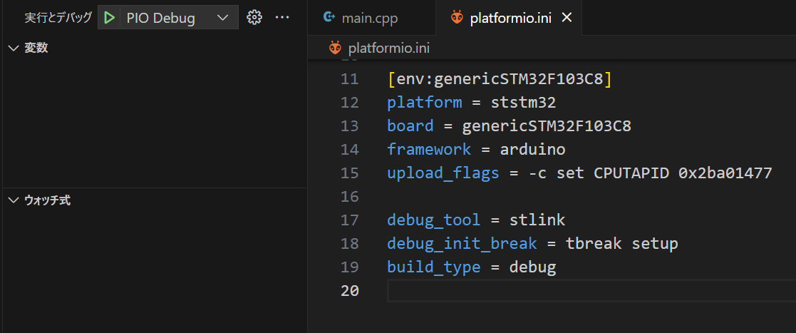
Of course, we would like to debug as well (laughs). Although I have a feeling that it won't be straightforward, I modify the platformio.ini file as follows:
```ini
[env:genericSTM32F103C8]
platform = ststm32
board = genericSTM32F103C8
framework = arduino
upload_flags = -c set CPUTAPID 0x2ba01477
debug_tool = stlink
debug_init_break = tbreak setup
build_type = debug
I execute debugging using the "PIO Debug" debug configuration defined in the default-created ".vscode/launch.json" of the project.
As expected, an error occurred.
PlatformIO Unified Debugger -> https://bit.ly/pio-debug
PlatformIO: debug_tool = stlink
PlatformIO: Initializing remote target...
xPack Open On-Chip Debugger 0.12.0-01004-g9ea7f3d64-dirty (2023-01-30-15:04)
Licensed under GNU GPL v2
For bug reports, read
	http://openocd.org/doc/doxygen/bugs.html
hla_swd
Info : The selected transport took over low-level target control. The results might differ compared to plain JTAG/SWD
Info : tcl server disabled
Info : telnet server disabled
Info : clock speed 1000 kHz
Info : STLINK V2J37S7 (API v2) VID:PID 0483:3748
Info : Target voltage: 3.227423
Warn : UNEXPECTED idcode: 0x2ba01477
Error: expected 1 of 1: 0x1ba01477

.pioinit:13: Error in sourced command file:
Remote communication error.  Target disconnected.: No such file or directory.
It seems that the debugger (OpenOCD) is detecting a mismatch in the CPUTAPID and causing an error.
Warn : UNEXPECTED idcode: 0x2ba01477
Error: expected 1 of 1: 0x1ba01477
It appears necessary to specify the CPUTAPID when executing the debugger.
I modified the platformio.ini file as follows (replace <User Folder> with your own path):
[env:genericSTM32F103C8]
platform = ststm32
board = genericSTM32F103C8
framework = arduino
upload_flags = -c set CPUTAPID 0x2ba01477

debug_tool = stlink
debug_init_break = tbreak setup
build_type = debug
debug_server =
  C:\Users\<User Folder>\.platformio\packages\tool-openocd\bin\openocd.exe
  -s C:\Users\<User Folder>\.platformio\packages\tool-openocd\scripts
  -f interface\stlink.cfg
  -c "transport select hla_swd"
  -c "set CPUTAPID 0x2ba01477"
  -f target\stm32f1x.cfg
  -c "reset_config none"
I execute debugging again.
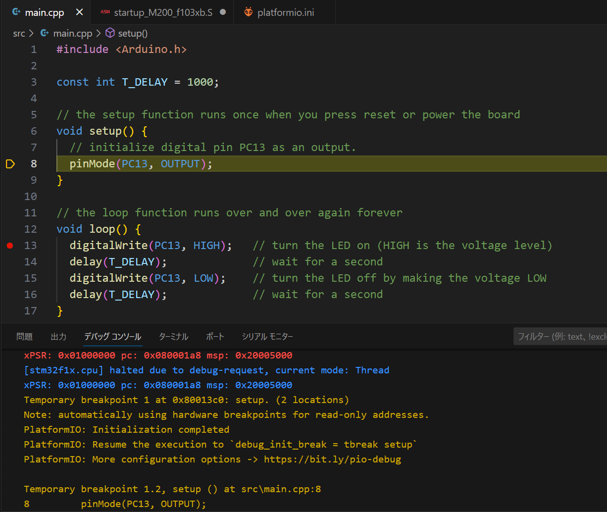
This time it was successful. The code in the 'setup' function is halted at the breakpoint.
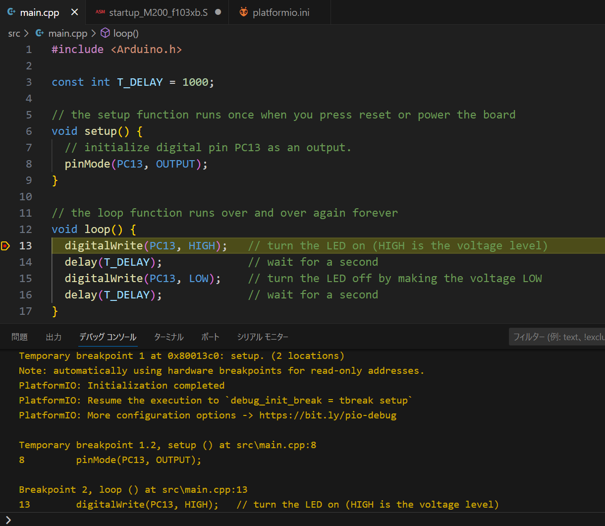
I press the run button to execute up to the next breakpoint. It stops at the breakpoint on line 13.
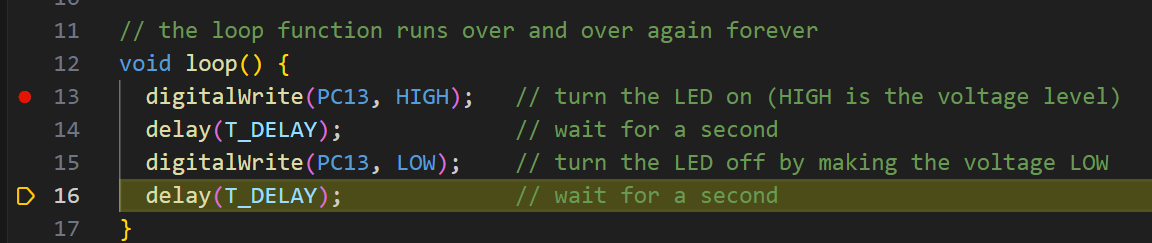
Step execution was also possible.
Conclusion
#Using the STM32F103C8T6 microcontroller board (although it is a clone), ST-Link V2 clone, Arduino IDE, and Platform IO, I was able to write and execute an LED blinking program. Additionally, I confirmed that debugging execution from Platform IO could stop at breakpoints and perform step execution. Both the microcontroller board and the debugger are very affordable, so why not give it a try?