Challenging Christmas Illuminations with Electronic Work
Back to TopTo reach a broader audience, this article has been translated from Japanese.
You can find the original version here.
This is the article for the 22nd day of the Mamezou Developer Site Advent Calendar 2023.
Christmas is just a few days away. Illuminations are shining everywhere in the city. I decided to try making Christmas illuminations at home using electronic work.
The goals were set as follows:
- Do not use a microcontroller
- React to people approaching the tree with a motion sensor
- Alternately light up the LEDs decorated on the tree
- Powered by a 5V battery
- Circuit is wired on a breadboard with solid jumper wires (considering appearance)
- Make as much as possible with what's available[1]
Power Supply
#I used a leftover 9V battery (which only outputs 7V) and stepped it down to 5V. I used a simple circuit with a three-terminal regulator that I had made before.
This three-terminal regulator converts voltages from 6V to 16V to 5V. If the current consumption is high, it generates heat, so a heatsink is necessary. However, since I am not flowing a large current (like 2A) for a long time, it is not necessary, but I am using one that I made before.
Tree Decoration
#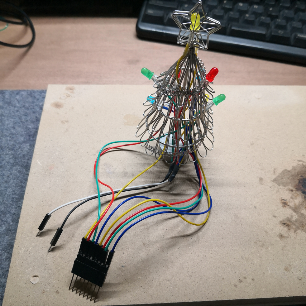
The LEDs decorated on the tree are common ones used in electronic works. I have soldered and extended the terminals of 8 yellow, red, green, and blue LEDs with 16 wires.
Also, since the tree is made of metal, the wires need to be insulated, and the soldered parts have been coated with an insulating film.
Initially, I thought about reducing the number of wires by connecting all the cathodes (negative terminals) of the LEDs to the tree, which would serve as GND (0V). However, due to the mechanism of the circuit that makes the LEDs blink alternately, it could not be done with one GND (lack of knowledge), so I grouped the GNDs by system. In the end, I modified it to connect to the circuit with a total of 10 wires.
If the LEDs were connected in series, the wiring would be simple with only four wires. However, since LEDs require different voltages (forward voltage) depending on their color, the brightness would vary. Therefore, I connected them in parallel and attached resistors to each LED to limit the current and adjust the brightness.
Transistor Operation
#Transistors play a major role in the circuit I created. A transistor acts as an electrical switch, turning the flow of current on and off, and controlling a large current with a small one.
![]()
B: Base, C: Collector, E: Emitter.
When the voltage between the base and emitter exceeds 0.6V, current flows between B-E, turning the switch ON. This current acts as a primer, allowing current to flow between C-E. At this time, the current flowing between C-E can be more than 100 times the current flowing between B-E. This allows for electrical ON/OFF control and adjustment of large currents with a small one.
Circuit Diagram
#I tried drawing a circuit diagram for the first time by imitating others. I used a CAD for circuit diagrams called BSch3V which is easy to use.
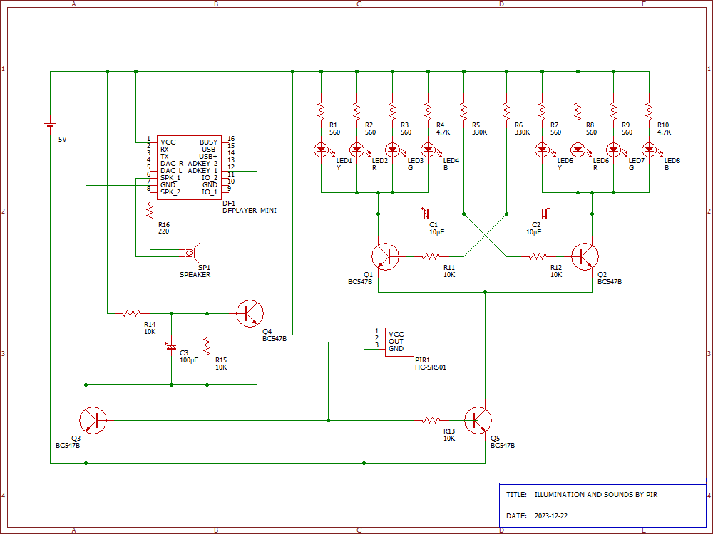
The final circuit[2] turned out as shown in the diagram above.
The initial version only had the motion sensor (PIR1) in the lower center and the blinking circuit on the right half, but later I added the music playback circuit on the left half.
Blinking Circuit
#The blinking of the LEDs is achieved by assembling a circuit called a non-stable multivibrator. It seems to be a basic circuit design. It's like the 'Hello World' of software, the 'teapot' of 3D models, or the 'L blinking' of microcontrollers (although it feels more difficult than that).
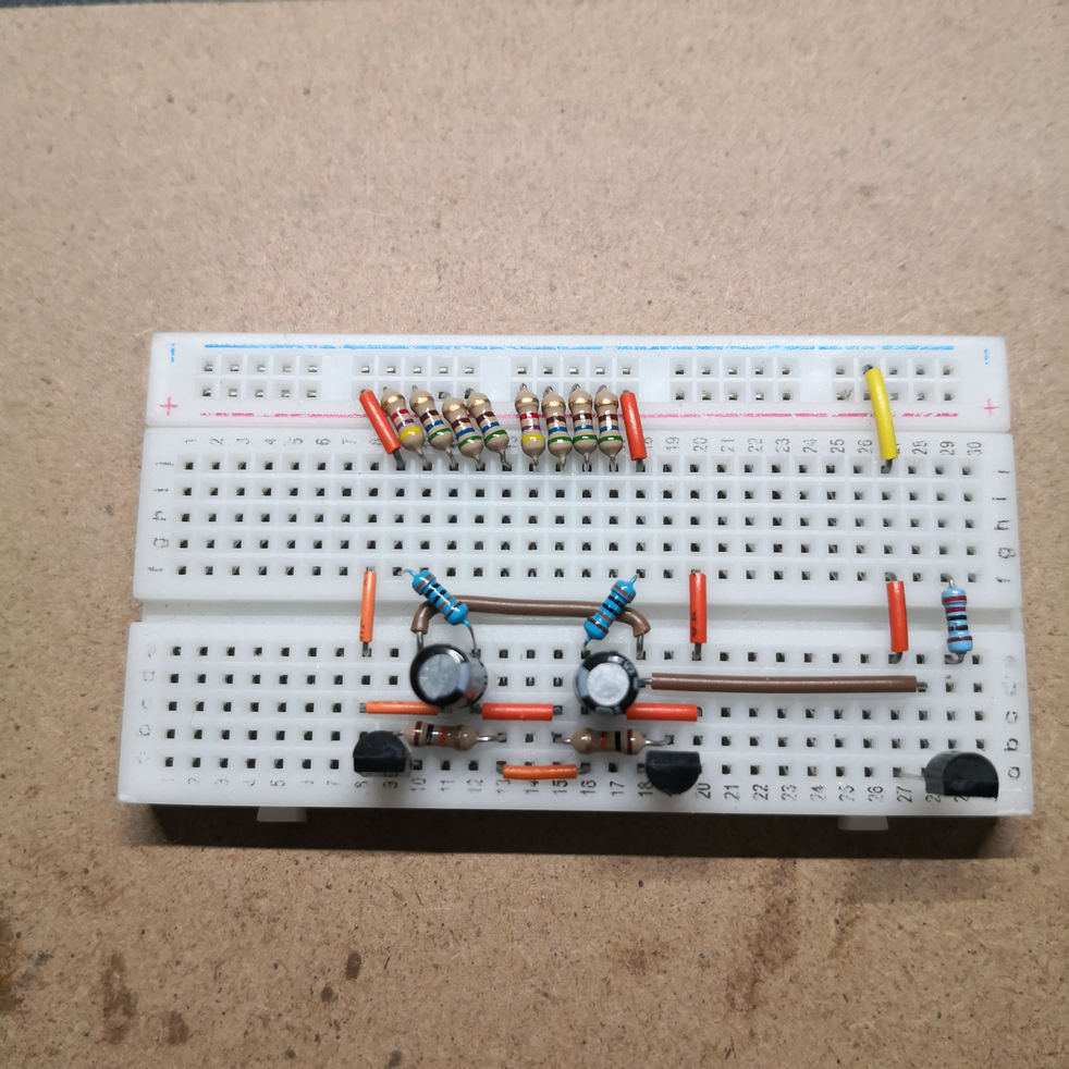
The cables of the LEDs are inserted below the row of resistors in the center. The two capacitors alternately charge and discharge, controlling the transistor switch and allowing only one side to be powered at a time, making the LEDs blink.
The flow of voltage and current is complex, and I do not fully understand the detailed behavior. Intuitively, I understand that increasing the resistance value or capacitor capacity will slow down the blinking. I adjusted R5, R6, C1, C2 to achieve an appropriate blinking speed.
The transistor at the bottom right of the photo, Q5, acts as the power switch for the blinking circuit. Later, I will connect PIR1's OUT (pin 2) to it.
Power Saving and Brightness Adjustment
#The tree's blinking is set with a large resistor to reduce power consumption, resulting in a magical light that gradually brightens and dims like the light of a firefly, rather than blinking.
PIR Motion Sensor
#The PIR (Passive Infra-Red) motion sensor detects changes in the amount of infrared emitted by people and reacts to the movement of people nearby. The key is that it only detects when there is movement; it does not detect if someone is standing still.
The sensor I used can adjust the detection distance and the duration of the detection signal with a variable resistor. I have set the detection distance to about 3 meters and the detection signal duration to about 30 seconds.
When the detection signal is ON, PIR1's OUT becomes ON (HIGH). At this time, I connected PIR1's OUT to the base of Q5 so that the power for the blinking circuit turns ON. I also connected it to the base of Q3 for the power of the music playback circuit mentioned later.
Having reached the target so far, I set the following additional goals:
- Play music along with the blinking of the LEDs
- Put it in a skeleton case to make it portable
Music Playback Circuit
#The combination of the music playback module and the PIR sensor on the left side of the circuit diagram is as follows.
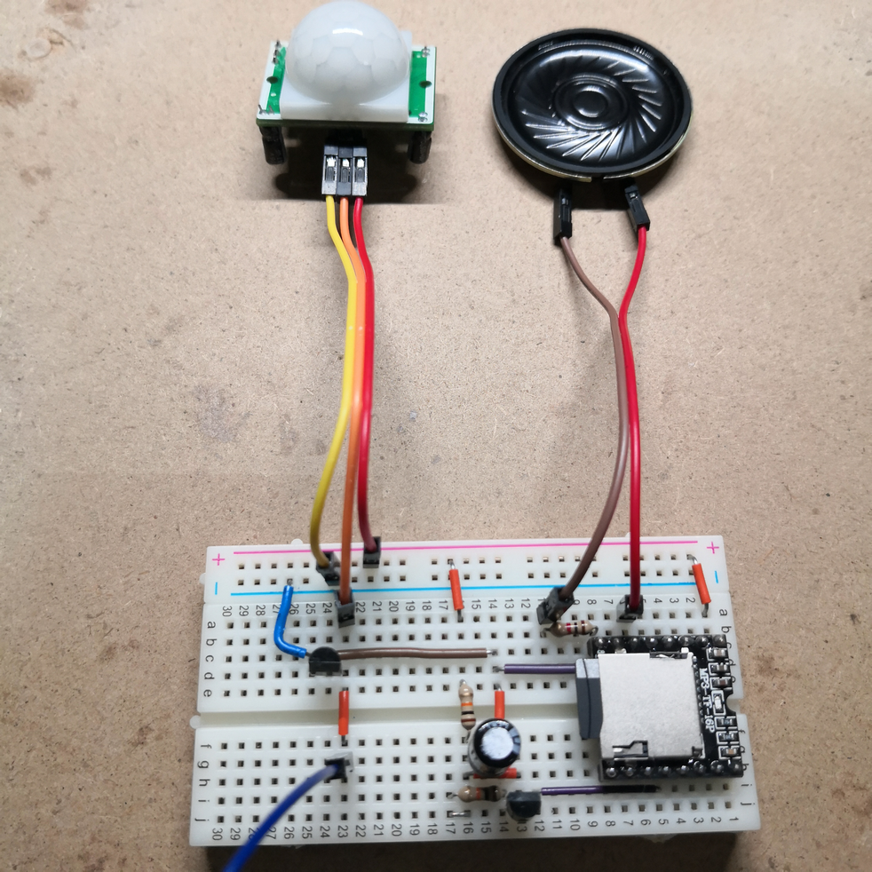
The transistor below the PIR sensor in the photo is Q3 in the circuit diagram, and it acts as the power switch for the music playback module. The volume of the speaker is adjusted by the resistance value of resistor R16.
Music Playback Module
#To produce sound, it is necessary to synthesize waves of various frequencies and convert them into voltage changes. Since I couldn't build a circuit myself, I used a music playback module[3].
This module is well-designed and can play multiple mp3 files written on a microSD card. Moreover, it can be controlled externally to play, stop, adjust the volume, repeat, and select tracks.
Playback Timing Processing
#To generate a signal, it is necessary to pull the HIGH wire coming out of ADKEY_1 (pin 11) to GND, but before that, the music playback module needs to be powered on. For this, I referred to a power-on delay circuit.
The power-on delay circuit, as the name suggests, is a circuit that delays operation when the power is turned on. It's like the setTimeout() function in JavaScript. The circuit is composed of resistors R14, R15, capacitor C3, and transistor Q4 in the lower left of the circuit diagram. When the collector-emitter of transistor Q3 conducts, power is supplied to the music playback module. The voltage of capacitor C3 gradually rises from 0V, and when it reaches 0.6V, the collector-emitter of transistor Q4 conducts, pulling ADKEY_1 to GND and starting the music playback. The time it takes to drop is adjusted by the resistance value of R14 and the capacitor capacity of C3.
However, the music did not play when I turned the power on a second time. When the power is turned off, the charge stored in capacitor C3 has no escape, so it remains stored and acts like a battery. Therefore, when the power is turned on the second time, it immediately reaches a voltage above 0.6V. As a result, transistor Q4 also turns ON when the music playback module is powered on, keeping ADKEY_1 in the GND state, so no signal is generated, and no music plays.
To resolve this, I placed resistor R15 in parallel with capacitor C3 and set the resistance value to 10k ohms. This way, almost no current flows through R15 when the power is ON. However, when the power is OFF, the energy stored in capacitor C3 is consumed in about one second. It's interesting that it starts moving when the power is OFF, like the elves in the shoemaker's tale in Grimm's fairy tales.
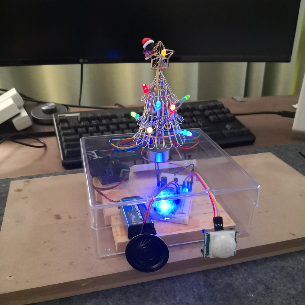
Case
#I used a leftover plastic case and modified it. I used a router and an electric drill to make holes in the lid and pass the wires through. I didn't think much about installation, so it was challenging to close the lid with the speaker and tree still connected to the internal circuit.
Also, the case was slightly deep, so I placed a 'kamaboko' board at the bottom to raise it. It's good to keep things around.
Due to lack of time, the speaker and PIR sensor were left hanging without being fixed.
Power Consumption
#I measured the power consumption of each module when the PIR sensor did not detect and when it detected.
| Module | Undetected | Detected |
|---|---|---|
| PIR Sensor | 0.1mA | 1.6mA |
| Tree (LED) | 0mA | 10~15mA |
| Music Playback Module | 0mA | 30mA |
| Speaker | 0mA | 0.1mA |
| Overall | 0.1mA | 40~45mA |
The PIR sensor always has a current flowing through it, but the power consumption is very low at 0.1mA. Other modules only operate for a few tens of seconds while the PIR sensor is generating a detection signal. Even during detection, the total current flow is only up to 45mA.
There are 8 LEDs, but since they are blinking, only 4 are actually lit, and the power consumption is low because the brightness is reduced. However, the music playback module consumes more power than expected. Probably because the LED of the music playback module lights up quite brightly while the music is playing.
The capacity of a dry cell battery is said to be several hundred mAh (can be used for several hundred mA for one hour). Assuming a 5V battery with a capacity of 450mAh is used, the power consumption would allow for about 10 hours of continuous operation.
Video
#Please take a look at the completed product. Please be careful as it makes a sound!!
A black cat Santa (Fuchineko), which I got as a prize from a certain cafe, is hanging from the star on the top of the tree. The sensor reacts even at a distance of about 3 meters, but I'm waving my hand to show that it detects people and makes a sound 😀
You can download the circuit diagrams, music, and video here.
Comparison with Microcontroller Control
#In Arduino's 'L blinking', the following example is described. (Blink 'L' every 500[msec])
void loop()
{
   digitalWrite(pin number N, HIGH);
   delay(500);
   digitalWrite(pin number N, LOW);
   delay(500);
}
What if you want to blink a second LED every 300[msec]? (or blink 'L' only while pressing a button)
void loop()
{
   digitalWrite(pin number N, HIGH);
   delay(500);
   digitalWrite(pin number N, LOW);
   delay(500);
   digitalWrite(pin number M, HIGH);
   delay(300);
   digitalWrite(pin number M, LOW);
   delay(300);
}
This does not work well because it calls delay() within the loop function, putting the CPU in a wait state to achieve 'L blinking'. It's often said not to sleep in the loop.
Since Arduino does not support multithreading, it is not possible to execute 'L blinking' in parallel.
Therefore, you might use a library that pretends to be multithreading, or synchronize every 100[msec] to do something like the FizzBuzz problem.
Ah, how difficult it is.
On the other hand, parallel circuits are a basic method of using electronic circuits. You can execute processes in parallel as much as you want. It might be possible to realize 'L blinking' on the circuit side as well.
In Conclusion
#Until now, I've only played around with circuits and modules, but this was the first time I made something serious. I managed to complete it through trial and error without knowledge of circuit design, and I am very satisfied. I'd like to make something again.
Have a wonderful Christmas! 🎄🎅✨
Eventually, I had to purchase only the missing transistors and a music playback module [with speaker] ↩︎
The circuit consists of transistors (BC547B), but in the actual circuit, different transistors (2SC1815) were used where there was a shortage. ↩︎
DFPlayer Mini. It was 890 yen with a speaker on Amazon. ↩︎